一 : 1N5300-1中文资料
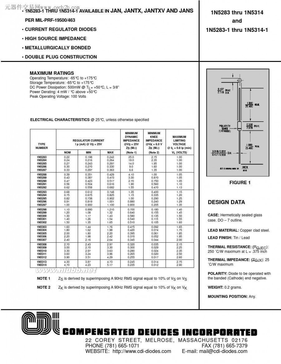
n5300 1N5300-1中文资料

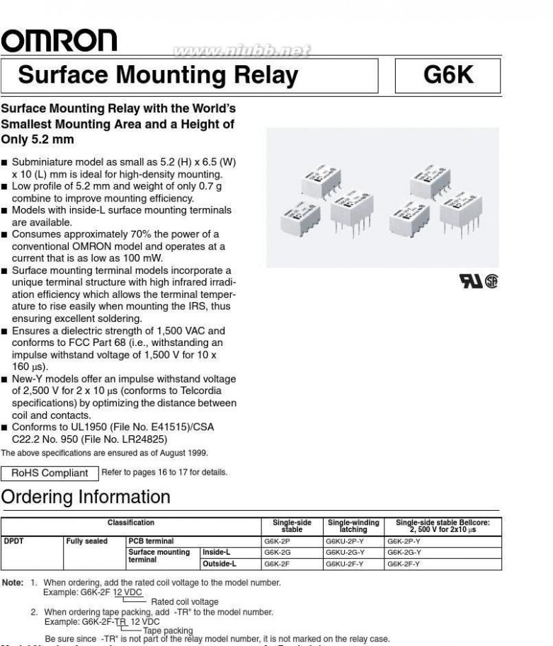
二 : G6K-2F中文资料
F:Outside-L surface mounting terminalG:Inside-L surface mounting terminalP:PCB terminal4.Approved standards
1.Relay function
None:UL, CSA
None:Single-side stable modelDoes not conform to Telcordia specificationsU:Single-winding latching modelY:UL, CSA2.Contact formConforms to Telcordia specifications: 2,500 V for 2 x
10 μs2:DPDT
5.Rated Coil Voltage
3, 4.5, 5, 12, 24 VDC
91
2f G6K-2F中文资料
Application Examples
Telephones, communications equipment, measurement devices, office automation machines, and audio–visual products.
Specifications
Contact mechanism:Bifurcated crossbar Ag (Au-alloy contact)Enclosure ratings:Fully sealed■
Coil Ratings
Single-side Stable Models
G6K-2F, G6K-2G, G6K-2PRated voltageRated currentCoil resistanceMust operate voltageMust release voltageMax. voltagePower consumptionNote:
3 VDC33.0 mA91 ?
4.5 VDC23.2 mA194 ?
5 VDC21.1 mA237 ?
12 VDC9.1 mA1,315 ?
80% max. of rated voltage10% min. of rated voltage
150% of rated voltage at 23°C to 70°CApprox. 100 mW
1.The rated current and coil resistance are measured at a coil temperature of 23°C with a tolerance of ±10%.2.The operating characteristics are measured at a coil temperature of 23°C.
3.The maximum voltage is the highest voltage that can be imposed on the relay coil instantaneously.
Single-side Stable Models (Bellcore Version)
G6K-2F-Y, G6K-2G-Y, G6K-2P-YRated voltageRated currentCoil resistanceMust operate voltageMust release voltageMax. voltagePower consumptionNote:
3 VDC33.0 mA91 ?
4.5 VDC23.2 mA194 ?
5 VDC21.1 mA237 ?
12 VDC9.1 mA1,315 ?
24 VDC4.6 mA5,220 ?
80% max. of rated voltage10% min. of rated voltage
150% of rated voltage at 23°C to 70°CApprox. 100 mW
1.The rated current and coil resistance are measured at a coil temperature of 23°C with a tolerance of ±10%.2.The operating characteristics are measured at a coil temperature of 23°C.
3.The maximum voltage is the highest voltage that can be imposed on the relay coil instantaneously.
Single-winding Latching Models (Bellcore Version)
G6KU-2F-Y, G6KU-2G-Y, G6KU-2P-YRated voltageRated currentCoil resistanceMust set voltageMust reset voltageMax. voltagePower consumptionNote:
3 VDC33.0 mA91 ?
4.5 VDC23.2 mA194 ?
5 VDC21.1 mA237 ?
12 VDC9.1 mA1,315 ?
24 VDC4.6 mA5,220 ?
75% max. of rated voltage75% max. of rated voltage
150% of rated voltage at 23°C to 70°CApprox. 100 mW
1.The rated current and coil resistance are measured at a coil temperature of 23°C with a tolerance of ±10%.2.The operating characteristics are measured at a coil temperature of 23°C.
3.The maximum voltage is the highest voltage that can be imposed on the relay coil instantaneously.
92
2f G6K-2F中文资料
■Contact Ratings
Resistive load
0.3 A at 125 VAC; 1 A at 30 VDC
1 A
125 VAC, 60 VDC
1 ALoadRated loadRated carry currentMax. switching voltageMax. switching current
■Characteristics
ItemSingle-side stable models (double-pole)
G6K-2F, G6K-2G, G6K-2PG6K-2F-Y, G6K-2G-Y, G6K-2P-YSingle-winding latching modelG6KU-2F-Y, G6KU-2G-Y, G6KU-2P-Y
3 ms max. (approx. 1.2 ms)
3 ms max. (approx. 1.2 ms)Contact resistance (See note 1.)Operating (set) time (See note 2.)Release (reset) time (See note 2.)
Dielectric strengthCoil and contacts100 m? max.3 ms max. (approx. 1.4 ms)3 ms max. (approx. 1.3 ms)1,500 VAC, 50/60 Hz for 1 minInsulation resistance (See note 3.)1,000 M? min. (at 500 VDC)
Contacts of different 1,000 VAC, 50/60 Hz for 1 minpolarity
Contacts of same po-750 VAC, 50/60 Hz for 1 minlarity
Impulse withstand voltageCoil and contacts1,500 V (10 x 160 μs)2,500 V (2 x 10 μs), 1,500 V (10 x 160 μs)Contacts of different 1,500 V (10 x 160 μs)polarity
Contacts of same po-larity
Vibration resistanceDestruction: 10 to 55 Hz, 2.5-mm single amplitude (5-mm double amplitude) and 55 to 500 Hz,
300 m/s2 (approx. 30G)Malfunction: 10 to 55 Hz, 1.65-mm single amplitude (3.3-mm double amplitude) and 55 to 500 Hz,
200 m/s2 (approx. 20G)
Destruction: 1,000 ms2 (approx. 100G)
Malfunction: 750 ms2 (approx. 75G)
Mechanical: 50,000,000 operations min. (at 36,000 operations/hour)Electrical: 100,000 operations min. (with a rated load at 1,800 operations/hour)
10 μA at 10 mVDC
Operating: ?40°C to 70°C (with no icing or condensation)
Operating: 5% to 85%
Approx. 0.7 gShock resistanceEnduranceFailure rate (P level) (See note 4.)Ambient temperature Ambient humidityWeight
扩展:g6k 2f y / g6k 2f y 使用说明 / g6k 2f
Note:
Note:The above values are initial values.1.The contact resistance was measured with 10 mA at 1 VDC with a voltage-drop method.
2.Values in parentheses are actual values.
3.The insulation resistance was measured with a 500-VDC megohmmeter applied to the same parts as those used for checkingthe dielectric strength.
4.This value was measured at a switching frequency of 120 operations/min and the criterion of contact resistance is 50 ?. Thisvalue may vary depending on the switching frequency and operating environment. Always double-check relay suitability underactual operating conditions.93
2f G6K-2F中文资料
Engineering Data
Maximum Switching Power
Maximum coil voltage (%)
Switching current (A)
Ambient Temperature vs. Maximum Coil VoltageAmbient Temperature vs. Switching Current
Switching current (A)
AC resistive load
DC resistive load
Switching voltage (V)
Ambient temperature (°C)
Ambient temperature (°C)
Note: The maximum coil voltage refers to the maxi
mum value in a varying range of operating power voltage, not a continuous voltage.
Endurance
operations)Switching operations (x10 4
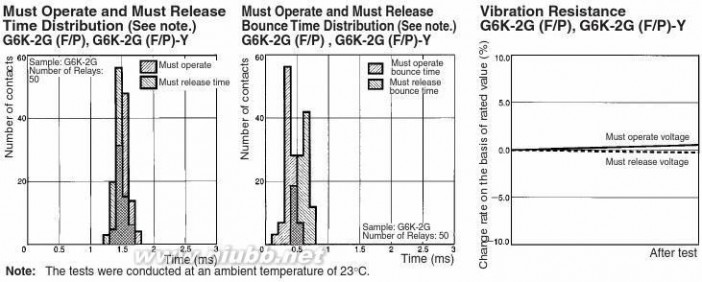
G6K-2G (F/P), G6K-2G (F/P)-Y
On the basis of rated voltage (%)
Ambient Temperature vs. Must
Operate or Must Release Voltage
Max. estimated value
Ambient Temperature vs. Must Set or Must Reset Voltage
G6KU-2G (F/P)-Y
On the basis of rated voltage (%)
Max. estimated value
30 VDC resistive load
Ambient temperature: 23°C Switching frequency: 1,800 operations/hour
125 VAC resistive load
Ambient temperature: 23°CSwitching frequency: 1,800 operations/hour
Must operate voltageMust release voltage
Switching current (A)
Ambient temperature (°C)Ambient temperature (°C)
Shock Malfunction
Energized
Not
energized
Electrical Endurance
(with Must Operate and Must Release Voltage) (See note.)
G6K-2G (F/P), G6K-2G (F/P)-Y
On the basis of rated voltage (%)
Sample: G6K-2G
Number of Relays: 10
Test conditions: 1 A resistive load at 30 VDC with an operation rate of 50%Switching frequency: 1,800 operations/h
Electrical Endurance
(Contact Resistance) (See note.)
G6K-2G (F/P), G6K-2G (F/P)-Y
Contact resistance (m?)
Sample: G6K-2G
Number of Relays: 10
Test conditions: 1 A resistive load
at 30 VDC with an operation rate of 50%Switching frequency: 1,800 operations/h
NO contactNC contact
Must operate
Contact resistance
Shock direction
Unit: m/s2
Sample: G6K-2G
Number of Relays: 10
Must release
Conditions: Shock is applied in ±X, ±Y, and ±Z di
rections three times each with and without energizing the Relays to check the number of contact malfunctions.
3
Operating frequency (x10 operations)
Operating frequency (x10 operations)Note: The tests were conducted at an
ambient temperature of 23?C.
3
Note: The tests were conducted at an
ambient temperature of 23?C.
94
2f G6K-2F中文资料
Note:
1.The tests were conducted at an ambient temperature of 23°C.
2.High-frequency characteristics depend on the PCB to which the Relay is mounted. Always check these characteristics includingendurance in the actual machine before use.

95
2f G6K-2F中文资料
Dimensions
Note:■
All units are in millimeters unless otherwise indicated.
DPDT
Mounting Dimensions (Top View)Tolerance: ±0.1 mm
Terminal Arrangement/Internal Connections (Top View)
G6K-2F
Note: Each value has a tolerance of ±0.3 mm.
Orientation mark
G6K-2G
Mounting Dimensions (Top View)Tolerance: ±0.1 mm
Terminal Arrangement/Internal Connections (Top View)
Note: Each value has a tolerance of ±0.3 mm.
Orientation mark
G6K-2P
Mounting Dimensions (Bottom View)Terminal Arrangement/Tolerance: ±0.1 mmInternal Connections
(Bottom View)Eight, 0.8-dia. holes
Orientation mark
Note: Each value has a tolerance of ±0.3 mm.
96
2f G6K-2F中文资料
G6K-2F-YMounting Dimensions (Top View)
Tolerance: ±0.1 mmTerminal Arrangement/Internal Connections (Top View)G6K-2G-YNote: Each value has a tolerance of ±0.3 mm.Orientation markMounting Dimensions (Top View)Tolerance: ±0.1 mmTerminal Arrangement/Internal Connections (Top View)
Orientation mark
Note: Each value has a tolerance of ±0.3 mm.
G6K-2P-YMounting Dimensions (Bottom View)Tolerance: ±0.1 mm
扩展:g6k 2f y / g6k 2f y 使用说明 / g6k 2f
Eight,
0.8-dia. holesTerminal Arrangement/Internal Connections (Bottom View)Orientation mark
Note: Each value has a tolerance of ±0.3 mm.
G6KU-2F-YMounting Dimensions (Top View)
Tolerance: ±0.1 mmTerminal Arrangement/Internal Connections (Top View)
Note: Each value has a tolerance of ±0.3 mm.Orientation mark
G6KU-2G-YMounting Dimensions (Top View)Tolerance: ±0.1 mmTerminal Arrangement/Internal Connections (Top View)G6KU-2P-YNote: Each value has a tolerance of ±0.3 mm.Mounting Dimensions (Bottom View)Terminal Arrangement/Internal Connections Tolerance: ±0.1 mmEight, 0.8-dia. holes(Bottom View)
Orientation markOrientation mark
Note: Each value has a tolerance of ±0.3 mm.
97
2f G6K-2F中文资料
Stick Packing and Tape Packing
Stick Packing
Relays in stick packing are arranged so that the orientation mark
of each Relay in on the left side. Fifty Relays are packed on one
stick.
Be sure not to make mistakes in Relay orientation when mounting
the Relay to the PCB.Stopper (gray)Orientation of Relays
Stopper (green)
Stick length: 520 mm (stopper not included)No. of Relays per stick: 50
Tape Packing (Surface Mounting Terminal
Models)
When ordering Relays in tape packing, add the prefix “-TR” to the
model number, otherwise the Relays in stick packing will be pro-vided.Tape Type:ETX7200 (EIAJ (Electronic Industrial Association of Japan))Reel type:RPM-16D (EIAJ)Relays per Reel: 900

1. Direction of Relay Insertion
Top tape (cover tape)Pulling directionOrientation mark3. Carrier Tape DimensionsG6K-2F, G6K-2F-Y, G6KU-2F-Y
Pulling direction
Carrier tapeEmboss tape
2. Reel DimensionsG6K-2G, G6K-2G-Y, G6KU-2G-Y
98
2f G6K-2F中文资料
Recommended Soldering Method
Temperature indicate the surface temperature of the PCBs.IRS Method (for surface mounting terminal models)(1) IRS Method (Mounting Solder: Lead)
(2) IRS Method (Mounting Solder: Lead-free)
Temperature (°C)
220 to245180 to200
Soldering
150
Preheating
?
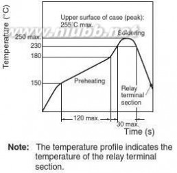
?In order to perform correct soldering, it is recommended that the correct soldering conditions be maintained as shown below on the leftside.
90 to 120
20 to 30
Time (s)
Correct Soldering
RelayTerminal
SolderLand
Incorrect Soldering
Insufficient amount of solder
Excessive amount of solder
PCB
Visually check that the Relay is properly soldered.■
Approved Standards
UL approval:UL1950 (File No. E41515)
CSA approval:C22.2 No. 950 (File No. LR31928)
Contact formDPDT
Coil rating
G6K-2G(F/P): 3 to 12 VDC
G6K(U)-2G(F/P)-Y: 3 to 24 VDC
Contact rating
1 A at 30 VDC0.5 A at 60 VDC0.3 A at 125 VAC
Number of test operations6,000
99
2f G6K-2F中文资料
Precautions
Refer to page25 for information on general precautions. Be sure to read these precautions before using the Relay.
Latching Relay MountingCorrect Use
Make sure that the vibration or shock that is generated from other Long-term Continuously ON Contacts
devices, such as relays in operation, on the same panel and Using the Relay in a circuit where the Relay will be ON continu-imposed on the Latching Relay does not exceed the rated value, ously for long periods (without switching) can lead to unstable
otherwise the Latching Relay that has been set may be reset or contacts because the heat generated by the coil itself will affect
vice versa. The Latching Relay is reset before shipping. If exces-the insulation, causing a film to develop on the contact surfaces.
sive vibration or shock is imposed, however, the Latching Relay We recommend using a latching relay (magnetic-holding relay) in
may be set accidentally. Be sure to apply a reset signal before this kind of circuit. If a single-side stable model must be used in
use.this kind of circuit, we recommend using a fail-safe circuit design
Maximum Allowable Voltagethat provides protection against contact failure or coil burnout.
The maximum allowable voltage of the coil can be obtained from Relay Handling
the coil temperature increase and the heat-resisting temperature Use the Relay as soon as possible after opening the moisture-of coil insulating sheath material. (Exceeding the heat-resisting proof package. If the Relay is left for a long time after opening the
temperature may result in burning or short-circuiting.) The maxi-moisture-proof package, the appearance may suffer and seal fail-mum allowable voltage also involves important restrictions which ure may occur after the solder mounting process. To store the
扩展:g6k 2f y / g6k 2f y 使用说明 / g6k 2f
include the following:Relay after opening the moisture-proof package, place it into the
?Must not cause thermal changes in or deterioration of the insu-original package and sealed the package with adhesive tape.
lating material.
When washing the product after soldering the Relay to a PCB,
?Must not cause damage to other control devices.use a water-based solvent or alcohol-based solvent, and keep the
?Must not cause any harmful effect on people.solvent temperature to less than 40°C. Do not put the Relay in a
?Must not cause fire.cold cleaning bath immediately after soldering.
Therefore, be sure to use the maximum allowable voltage beyond Soldering
the value specified in the catalog.Soldering temperature: Approx. 250°C (260°C if the DWS method
As a rule, the rated voltage must be applied to the coil. A voltage is used)
exceeding the rated value, however, can be applied to the coil Soldering time: Approx. 5 s max. (approx. 2 s for the first time and
provided that the voltage is less than the maximum allowable volt-approx. 3 s for the second time if the DWS method is used)
age. It must be noted that continuous voltage application to the
Be sure to adjust the level of the molten solder so that the solder
coil will cause a coil temperature increase thus affecting charac-will not overflow onto the PCB.
teristics such as electrical life and resulting in the deterioration of
Claw Securing Force During Automatic Mountingcoil insulation.During automatic insertion of Relays, make sure to set the secur-Coating
ing force of each claw to the following so that the Relays charac-The Relay mounted on the PCB may be coated or washed but do
teristics will be maintained.

not apply silicone coating or detergent containing silicone, other-wise the silicone coating or detergent may remain on the surface of the Relay.PCB Mounting
If two or more Relays are closely mounted with the long sides of the Relays facing each other and soldering is performed with infrared radiation, the solder may not be properly exposed to the
Direction A: 1.96 Ninfrared rays. Be sure to keep the proper distance between adja-Direction B: 4.90 N
cent Relays as shown below.Direction C: 1.96 N
Environmental Conditions During Operation, Storage, and
Transportation
Protect the Relay from direct sunlight and keep the Relay under normal temperature, humidity, and pressure.
If the Relay is stored for a long time in an adverse environment with high temperature, high humidity, organic gases, or sulfide gases, sulfide or oxide films will form on the contact surfaces. These films may result in unstable contact, contact problems, or functional problems. Therefore, operate, store, or transport the product under specified environmental conditions.
G6K-2G
2 mm min.
G6K-2F
2.7 mm min.
Two or more Relays may be closely mounted with the short sides of the Relays facing each other.
ALL DIMENSIONS SHOWN ARE IN MILLIMETERS.
To convert millimeters into inches, multiply by 0.03937. To convert grams into ounces, multiply by 0.03527.
Cat. No. K106-E1-04
100
扩展:g6k 2f y / g6k 2f y 使用说明 / g6k 2f
三 : S9012中文资料
元器件交易网www.cecb2b.com
s9012 S9012中文资料
元器件交易网www.cecb2b.com
扩展:s9012三极管中文资料 / s9012 pdf 中文资料 / 9012中文资料
四 : K2717中文资料


元器件交易网www.cecb2b.com
k2717 K2717中文资料


元器件交易网www.cecb2b.com
k2717 K2717中文资料


元器件交易网www.cecb2b.com
k2717 K2717中文资料


元器件交易网www.cecb2b.com
k2717 K2717中文资料


元器件交易网www.cecb2b.com
扩展:k2717 / k2717参数 / k2717引脚图
本文标题:中文资料-1N5300-1中文资料61阅读| 精彩专题| 最新文章| 热门文章| 苏ICP备13036349号-1