一 : 雷尼绍探针


CMM products technical speci? cation
H-1000-5050-19-AProbing systems for
co-ordinate measuring machines
雷尼绍探针 雷尼绍探针
Renishaw’s technology

Renishaw stands at the forefront of automated metrology, with the Group’s products providing manufacturers with the ability to machine components accurately, and perform measurement traceable to international standards. Probe technology, allows fast, highly repeatable measurements to be carried out on co-ordinate measuring machines (CMMs).
A wide range of automated probing systems has been developed to meet the needs of post-process inspection, for quality control.
During the manufacturing operation, probes used on computer numerically controlled (CNC) machine tools provide the measurement capability to automatically control the machining process. This eliminates the need for costly, time consuming manual procedures.
Renishaw gives extra capability to CNC machine tools and CMMs by enabling scanning and digitising of 3-dimensional (3D) forms to generate the necessary NC programs to produce either replica parts, or moulds and dies.
Renishaw has developed the Cyclone scanning machine and associated software, a cost-effective solution to stand-alone digitising.
The revolutionary manufacturing system, RAMTIC (Renishaw’s automated milling, turning and inspection centre), maximises the potential of existing machine tools, enabling milling, turning and inspection on a single machine, together with automated loading and unloading of materials and tools.CNC machine tools and CMMs bene? t from regular volumetric checking by Renishaw’s automated ball-bar and machine checking gauge. Comprehensive machine calibration can be undertaken, when necessary, using Renishaw’s innovative laser calibration systems.Renishaw has developed linear scale, laser interferometer and encoder systems for ? tting to a variety of machines, to provide axis displacement measurement. Dedicated lengths of rigid scale are not required, since Renishaw’s approach has been to produce ? exible scale that can be dispensed from a reel and cut to the required length.Renishaw has also applied its innovatory approach to produce a Raman microscope and accessories for 2D spectral analysis of materials in a non-destructive manner.From its leading market position, the Renishaw Group continues to expand its product range into ever increasing business sectors worldwide. Identifying and targeting new market opportunities has led to the continuous development and introduction of new, highly innovative products which signi? cantly enhance the manufacturing capabilities


in a wide range of industries.
雷尼绍探针 雷尼绍探针

Probing systems for
co-ordinate measuring machines
Introduction to CMM probing
CMMs are used for a wide variety of industry applications, especially for post-process inspection of manufactured components. Renishaw’s probes and probing systems have become the industry choice for rapid and accurate inspection. CMMs, which act as a quality reference, use probing
systems to replace traditional manually operated measuring instruments such as micrometers, vernier callipers and dedicated gauges.
Contents1
How to use this guide
2 Touch-trigger probes
without stylus module changing
3 Touch-trigger probes
with stylus module changing
Probe systems
Renishaw’s probe systems are available in a wide variety of
types to enable a best match for a particular application.
4 Scanning probes5 6 7 8 9
Manual probe heads
with integral M8/autojoint probe mount
Fitting the probe on the CMM
The probe is mounted on the CMM via a probe head. The
type of head is determined by the ? exibility and automation required. Renishaw has designed a range of probe heads for manual and automated systems.
Motorised heads maximise probing ef? ciency and give a 3-axis CMM, 5-axis capability. A motorised head can also be used with Renishaw’s autochange systems which allows rapid and automatic exchange of multiple probe types and extension combinations.
Manual probe heads
with integral TP20 stylus module mount
Motorised probe heads
servo type
Motorised probe heads
indexing type
Advanced control
Traditionally, scanning has been limited to relatively slow machines but Renishaw’s universal CMM controller family enables this function at speeds many times faster than was previously possible.
Interfaces and controllers
10 Change/storage racks
for autojointed probes/extensions
11 Extension bars
Accessories
The range of accessories enhances the basic system by
offering additional capability such as stylus changing for the probe, probe sensor changing for multiple probe requirements and extension bars to provide access to deep features. Renishaw supplies a comprehensive range of styli for
component inspection and scanning applications which are available in a variety of pro? les, sizes and ? ttings to best suit the probe employed and the components’ features and dimensions.
To avoid the risk of compromising measurement performance, always use a replacement stylus from Renishaw!
12 Shanks13 Accessories
14 Styli and custom design service15 Glossary of terms16 Product index
雷尼绍探针 雷尼绍探针

Probing systems for
co-ordinate measuring machines
How to use this guide
This TECHNICAL SPECIFICATIONS document is intended to help you select the most appropriate probing system for your CMM. The probing system includes the probe with stylus, the method of attachment of the probe to the CMM
by use of a probe head or simple shank, and the necessary
probe/head controlling interfaces.
Probe system selection
Before selecting the most appropriate probe system, you should clearly understand the scope of measurement applications to be addressed on your CMM. Renishaw’s product range covers all types of probing requirements, from simple touch-trigger point measurement through to advanced part pro? le scanning. Where a standard product proves not to be ideal, Renishaw’s custom design service is available to accommodate you requirements.
This technical speci? cations document is divided into sections that focus on the different parts of the probing system and indicates the particular bene? ts of each product. The technical information for each product is also given so that performance data can be compared where more than one product appears suitable.
Step-by-step selection procedure
Step 1 (see sections 5, 6, 7 and 8)Systems suitable for your CMM
Q? Which type of CMM do you have or wish to purchase?Manual CMM - go to sections 5/6 to see the family trees of probing systems that are suited to manual CMMs. Identify the probe(s) and probe head(s) that are of interest, and then proceed to steps 2 and 3 to ? nd out more information on these products and ? nalise your selection.
DCC CMM - go to sections 7/8 to see the family trees of probing systems that are suited to DCC CMMs. Identify the probe(s) and probe head(s) that are of interest, and then proceed to steps 2 and 3 to ? nd out more information on these products and ? nalise your selection.
NOTE: All probes shown in this document are suitable for use on DCC CMMs.
Step 2 (see sections 2/3/4)Probe selection
Detailed information on each probe is given in one of three sections as described below.
Contact trigger probes (see sections 2 and 3)
Discrete point, contact trigger probes (also called touch-trigger probes) are ideal for inspection of 3
dimensional prismatic parts and known geometries. These probes are highly versatile and are suitable for a diverse range of applications, materials and surfaces, and there is a wide range of accessories available for them. The probes are segregated into two sections here - probes without, and probes with stylus module changing. Stylus module changing is a very important consideration as it enables higher productivity and the ability to always select the best measurement solution for the application. A further distinction between contact trigger probes is their type of design. There are kinematic probes and electronic probes to choose from. Probe sizes vary due to the features of the probe. The larger kinematic probes are extremely robust and are very well suited to manual CMMs due to their large overtravel capability. The smaller probes are suited to applications where there is a need to access restricted spaces. Renishaw’s electronic probes offer extended life suitable for high density point pro? le measurement and also permit higher accuracy than kinematic probes. Depending on the type of CMM and the level of utility required, there is a choice between shank mounted, M8 thread or autojoint mounted probes. Renishaw’s autojoint mounted probes and extensions can be rapidly interchanged for increased ? exibility and productivity.
Contact scanning probes (see section 4)
Scanning is ideal for the inspection of geometric forms and full pro? le measurement where thousands of data points can describe the form more fully than a few discrete points. A large amount of information can be collected in a very short time giving better direct results. Renishaw’s range of ? xed and indexable type scanning probes offers high accuracy, excellent robustness and low contact force scanning. All Renishaw scanning probes feature rapid interchange between stylus con? gurations to further increase ? exibility and productivity.
雷尼绍探针 雷尼绍探针


Step 3 (see sections 5/6/7/8)Probe head selection
Having selected the probe type, refer again to the family trees (sections 5 and 6 for manual CMMs or sections 7 and 8 for DCC CMMs) to see which probe head(s) are suitable.Manual CMMs - are usually ? tted with shank-mounted probes or manual probe heads. Renishaw offer varieties of manual probe heads which are segregated into sections 5/6 here detailing manual probe heads with integral M8/autojoint or with integral TP20 stylus module mount. A further design consideration is the choice of ? xed or articulating/indexing manual head types. The type of probe head required can be determined by examining the features of each head and matching them to your requirements.
DCC CMMs - can be ? tted with either manual or motorised probe head systems, so the choice must be made having considered the applications of the CMM. Motorised heads are segregated into sections 7/8 here detailing servo type and indexing type motorised heads. Fitting the probe on a CMM using a motorised head is the easiest way to vastly improve the capability of the CMM and maximise productivity. The indexing type motorised heads are designed to position the probe at one of 720 positions, in 7.5° steps, so probing can be carried out at many angles. The repeatability of the head means that these positions can be recalled at any time without the need for re-quali? cation. This can save a great deal of time for the operator, and encourages system optimisation by applying the probe to the surface at the best angle for the most
accurate result. Servo type motorised heads provide almost unlimited angular positioning and are ideally suited to horizontal arm CMMs.
Step 4 (see section 9)
Probe / probe head, interface selection
The probe data in sections 2, 3 and 4 de? nes the electrical interface(s) compatible with the chosen probe. See section 9 for full details of probe interfaces.
The probe head data in sections 5, 6, 7 and 8 de? nes the type of controller required to integrate the probe head into the CMM. See section 9 for full details of probe head interfaces.
Step 5 (see sections 11 and 12)Extension bar / shank selection
For probes and probe heads that are shank mounted on the CMM, go to section 12 to choose the appropriate shank. Section 11 details a comprehensive range of extension bars to enhance the versatility of your probe system. Remember that Renishaw offers a custom design service if the type of shank/extension you require is not a standard product.
Step 6 (see sections 2, 3, 4 and 10)Changer system selection
Many of Renishaw’s probes, when ? tted to DCC CMMs, are capable of rapid automatic interchange between stylus con? gurations or even between different types of probe. Refer to sections 2, 3 and 4 to see if your chosen probe has change rack compatibility, and for details of these highly productive systems. Renishaw’s autochange rack systems allow rapid exchange between probe sensors and extensions with the Renishaw autojoint and are detailed in section 10.
Step 7 (see section 13)Accessories
Check the accessories section 13, for other accessories available for your chosen probe system.
Step 8 (see section 14)Stylus selection
Renishaw produces a wide range of styli designed to optimise measurement performance. A brief overview is given in section 14. Please also see Renishaw’s Styli and accessories guide (part number H-1000-3200) for comprehensive details.
NOTE: Section 15 contains a glossary of terms used in this document.
This document contains information on Renishaw’s current CMM products range. If you require additional information on these and discontinued products, please visit our website: www.renishaw.com
雷尼绍探针 雷尼绍探针

Probing systems for
co-ordinate measuring machines
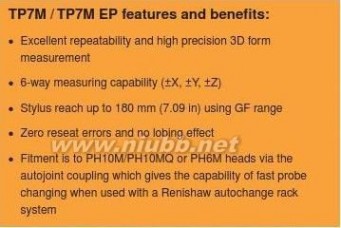
TP7M / TP7M EP probes
The TP7M range comprises electronic probes using strain gauge technology which gives higher accuracy )
)
than kinematic touch-trigger probes. Incorporating a m nnii 75multiwired autojoint connection, the TP7M is compatible n)
90..12(with the PH10M/PH10MQ motorised heads, PH6M ? xed ( mmprobe head, and the range of PEM extension bars.mm
)
mn02im 55The autojoint also allows fast probe changing, either 9 07.manually or automatically, with a Renishaw autochange m 20(rack system.
n)The enhanced performance TP7M EP is capable M4 × 0.7 thread
of achieving a 3D accuracy of <0.6 μm tested to ISO 10360 Pt 2.
16°
16°
5 mm (0.20 in)+Z overtravelMaximum 5 mm (0.20 in)XY overtravel
-Z overtravel
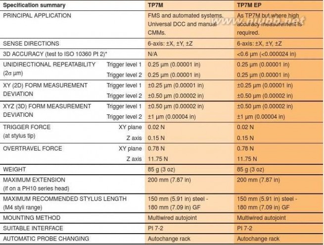
PI 7-2 probe interface
The PI 7-2 interface has two switchable levels of trigger sensitivity to accommodate differing applications. Please see section 9 for full details.
Above data applies for test conditions as follows: Stylus length 50 mm (1.97 in) Stylus velocity 240 mm/min (1.57 ft/min)* Test performed on a CMM speci? cation U3 = 0.48 μm + L/1000
雷尼绍探针 雷尼绍探针


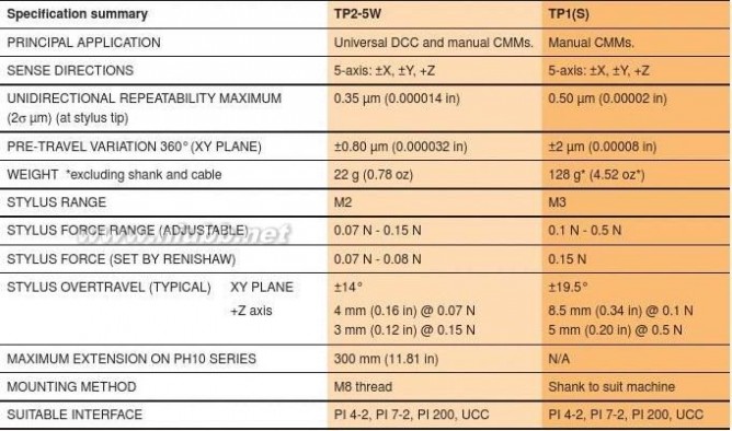
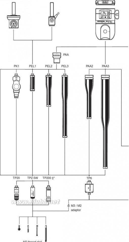
TP2-5W probesM8 × 1.25 threadThe TP2-5W is one of Renishaw’s best known products. It is a 13 mm (0.51 in)
diameter standard kinematic touch-trigger probe with an M8 thread mount. Its
adjustable stylus force enables the probe to support a wide range of styli.
The TP2 is small, light and compatible with a wide range of accessories, and
is suitable for manual and DCC CMMs.

)n
i
mm
5
.
1
( 2 in)
)m
n
im
5833
.
(
mm
m 9
n)
M2 × 0.4 threadimum 14°14°
ertravel
TP1 (S) probe+Z overtravel
4.0 mm (0.16 in)This large, robust kinematic probe has a high degree of overtravel and is
shank mounted, making it ideal for use on manual CMMs. The probe signal is
carried to the CMM via an external cable and the probe has adjustable stylus
force to help optimise its performance.

))n
in i
9
8
.
m 5
.
01
(
(
n)mm
mm
5614
M3 × 0.5 thread
mum 19.5°19.5°travel+Z overtravAbove data applies to test conditions as follows: Stylus length 10 mm (0.39 in) [re TP2-5W] or 31 mm (1.22 in) [re TP1(S)].Stylus velocity 480 mm/min (1.57 ft/min). Stylus force 0.07-0.08 N [re TP2-5W] or 0.15 N [re TP1(S)].
雷尼绍探针 雷尼绍探针

Probing systems for
co-ordinate measuring machines
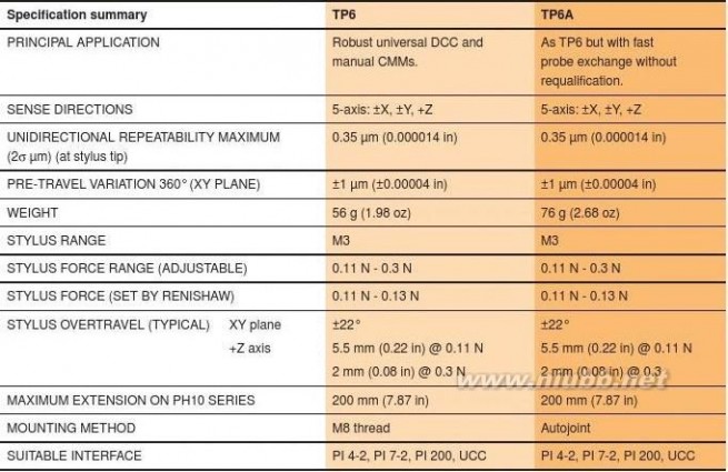
TP6 / TP6A probes
M8 × 1.25 thread
The TP6 is an M8 thread mounted probe while the TP6A has an autojoint, which means that it
)can be changed quickly and easily without the n)
imm n 1need to re-qualify stylus tips. The probe design
i 96.51is robust with large overtravel and adjustable in).(0 ( mtrigger force.

mm mm m1 54in)
1M3 × 0.5 thread
22°22°
+5Maximum
))
nnii mm
3389)
..n)
n11((i
95mm.0mm ( 59m.64m m4 n)
5122°22°
+Z ove5.5 mm
Above data applies to test conditions as follows: Stylus length 21 mm (0.83 in).Stylus velocity 480 mm/min (1.57 ft/min). Stylus force 0.11-0.13 N
雷尼绍探针 雷尼绍探针


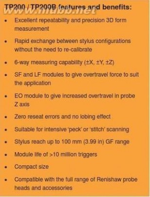
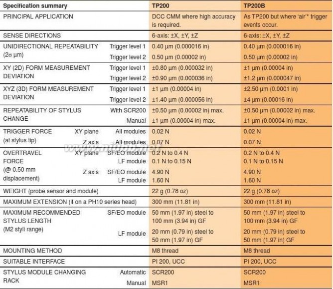
TP200 / TP200B modular probes
The TP200/TP200B are electronic probes using strain gauge technology, which gives higher accuracy than
kinematic touch-trigger probes. They combine outstanding metrology performance with superior functionality to
produce a highly versatile DCC CMM probing system with excellent productivity.
The TP200 system components are:? TP200 probe body – the standard model
? TP200B probe body – a variant model with increased vibration tolerance
?
TP200 stylus module – choice of ? xed overtravel forces: ‘SF’ (standard force) or ‘LF’ (low force)
There is also the ‘EO’ (extended overtravel) module, which has the same overtravel force as the ‘SF’ but provides increased operating range and protection in the probe Z axis? PI 200 probe interface?
SCR200 stylus changing rack
TP200 probe body
The TP200 probe incorporates micro strain gauge
transducers, delivering excellent repeatability and accurate 3D form measurement even with long styli. The sensor technology gives sub-micron triggering performance and eliminates the lobing characteristics encountered with standard probes. The solid-state ASIC electronics within the probe ensure reliable operation over millions of trigger points.
TP200B probe body
The TP200B probe uses the same technology as TP200 but has been designed to have a higher tolerance to
vibration. This helps to overcome the problem of ‘air’ trigger generation which can arise from vibrations transmitted through the CMM or when using longer styli with faster positioning speeds.
NOTE: We do not recommend the use of TP200B with the

LF module or cranked/star styli.
雷尼绍探针 雷尼绍探针

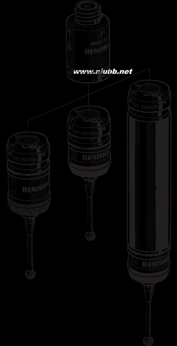
Probing systems forco-ordinate measuring machines TP200 stylus moduleM8 × 1.25 threadThe stylus module is mounted on the probe via a highly repeatable magnetic kinematic 5 mjoint, providing a rapid stylus changing capability and probe overtravel protection.Status LEDs(0.2There are three modules available, with two different overtravel forces:? The SF (standard force) module is mm 30 msuitable for most applications. in)(1.1? The LF (low force) module is recommended for use with small precision Kinematic ball styli or on delicate materials.planeSF/L? The EO (extended overtravel) module
is recommended for use when mm EO increasing the speed of the CMM in)may lead to stopping distances which exceed the overtravel range provided in the SF/LF modules. The EO module 0.4 threadSF/LF 4.5 mm (0.18 in)has an additional 8 mm (0.32 in) of EO 12.5 mm (0.49 in)overtravel in the probe Z axis to protect 14°14°+Z overtravelagainst damage to the sensor in such circumstances. Overtravel force is the Maximum 4 mm (0.16 in)same as the SF module.XY overtravel-Z overtravel by separation of
the module from the sensor
PI 200 probe interface
The PI 200 is a unit capable of the automatic recognition and interfacing of TP200/B and also conventional touch-trigger probes (TP2, TP6, TP20). Two switchable levels of probe trigger sensitivity are provided to accommodate differing applications. The PI 200 interface is covered fully in section 9.
SCR200 stylus changing rackThe SCR200 provides rapid, automatic changing of stylus modules without the need to re-qualify stylus tips. The SCR200 is powered entirely by the PI 200 and provides features to facilitate safe 245 mm (9.65 in)stylus changing.
MSR1 module storage rack For manual storage of modules - see section 13.)
n
i
4
Probe maintenance8
.
7
(
m
CK200 (Renishaw part number A-1085-0016) is m a specialised cleaning material supplied for the 0
9
1SCR200
removal of contamination from the location faces of the magnetically retained kinematic couplings of the TP20, TP200 and SP25M probe systems. The frequency of cleaning should be determined according to the conditions of use.
雷尼绍探针 雷尼绍探针


Above data applies for test conditions as follows: Stylus length 50 mm (1.97 in) Stylus velocity 480 mm/min (1.57 ft/min).* Air trigger (or false trigger). The TP200B reduces probe triggers that may be caused by vibrations.
雷尼绍探针 雷尼绍探针

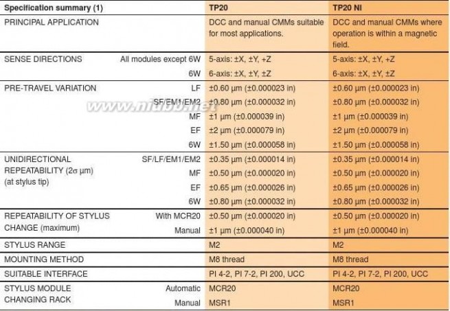
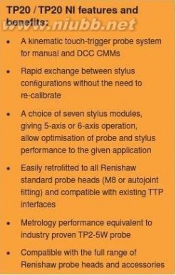
Probing systems forco-ordinate measuring machines TP20 / TP20 NI modular probesThe TP20 is a 5-way or 6-way kinematic touch-trigger probe. Its two piece design comprises a probe body and detachable stylus module(s), which gives the ability to change stylus con? gurations either manually or automatically without re-quali? cation of the stylus tips, providing signi? cant time savings in inspection routines.A direct replacement for the industry standard Renishaw TP2 probe, the TP20 probe system brings a range of new bene? ts to manual and DCC CMM applications, and can easily be retro? tted to existing TP2 installations.The TP20 can be used on a wide range of
Renishaw’s manual or motorised probe heads, either by direct mounting using the standard M8 thread or, alternatively, by using a PAA# adaptor to connect to an autojoint.
The system components are:
? TP20/TP20 NI probe body
? TP20 stylus module – seven module variants allow for optimisation of performance to suit the application
? MCR20 module changing rack – automatic operation
? The TP20 probe system may be used with Renishaw’s PI 4-2, PI 7-2 or PI 200 probe interfaces (see section 9)
TP20 probe body
The TP20 probe body houses one half of the highly repeatable magnetic kinematic coupling that attaches the stylus module and body. The body also contains a magnetic proximity switch to inhibit triggering of the probe during automatic module changing with MCR20.
NOTE: If the probe is operated close to magnetised parts/clamping etc, the probe
trigger may become inhibited. Countermeasures include the use of long styli, stylus extensions or body orientation to increase the distance to the magnetic source. Alternatively, use the TP20 NI probe body.
TP20 NI probe body
The TP20 NI probe differs from the TP20 body in that it is not affected by magnetic ? elds. However the probe trigger must be inhibited through
software during change cycles using the MCR20.M2 × 0.4 thread+Z overtravel-Z overtravelSF/EM1/EM2 4 mm (0.16 in)6W 1.5 mm (0.06 in)
LF 3.1 mm (0.12 in)
MF 3.7 mm (0.15 in)
EF 2.4 mm (0.09 in)
6W 4.5 mm (0.18 in)
雷尼绍探针 雷尼绍探针


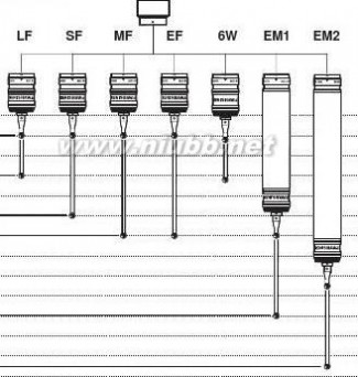
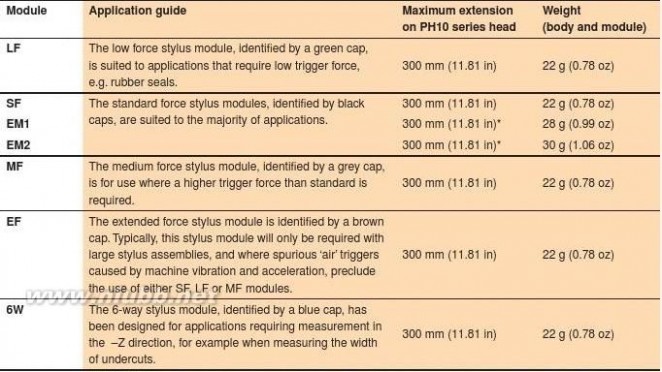
TP20 stylus module
The TP20 stylus module houses the kinematic switching touch sensor mechanism, carries
the stylus assembly and provides overtravel in ±X, ±Y and +Z axes (or ±Z in the case of
TP20 6-way module). The stylus mounting thread accepts styli from the Renishaw M2 range.
A range of seven, application speci? c, stylus modules is available, being identi? ed by coloured caps: ? SF - Standard force stylus module(black cap)
? LF - Low force stylus module(green cap)
? MF - Medium force stylus module(grey cap)
? EF - Extended force stylus module(brown cap)
? 6W - 6-way stylus module(blue cap)
? EM1 SF - Standard force extension module
?
EM2 SF - Standard force extension module
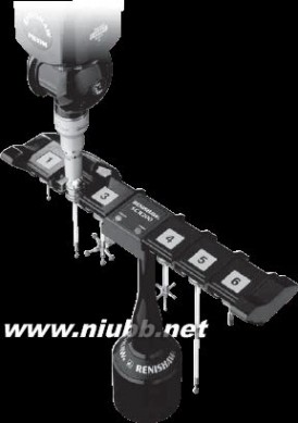
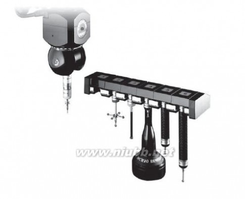
MCR20 module changing rack
The MCR20 probe module changing rack is designed to securely store stylus modules ready for rapid automatic changing, whilst protecting mating surfaces from any airborne contaminants within the working environment.
MSR1 module storage rack
For manual storage of modules - see section 13.
Probe maintenance
CK200 (Renishaw part number A-1085-0016) is a specialised cleaning material supplied for the removal of contamination from the location faces of the magnetically retained kinematic couplings of the TP20, TP200 and SP25M probe systems. The frequency of cleaning should be determined according to the conditions of use.
10 mm (0.39 in)30 mm (1.18 in)
50 mm (1.97 in)60 mm (2.36 in)100 mm (3.94 in)125 mm (4.92 in)Stylus comparison
200 mm (7.87 in)
15 mm (0.59 in)
)
ni 17.5( mm60 mm 54(2.36 in)
1MCR20
?55 mm
雷尼绍探针 雷尼绍探针

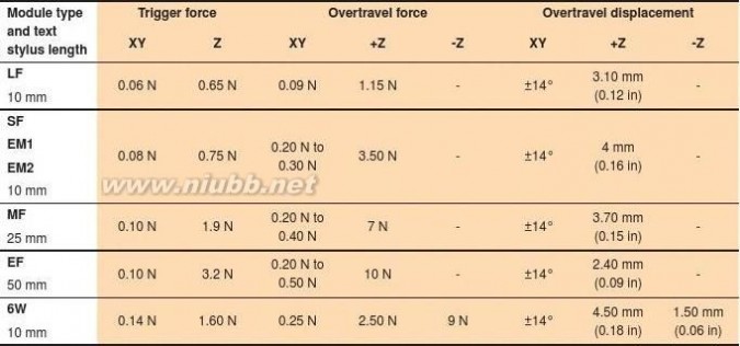
Probing systems forco-ordinate measuring machines Above data applies for test conditions as follows: Stylus length 10 mm (0.39 in). Stylus velocity 480 mm/min (1.57 ft/min)
雷尼绍探针 雷尼绍探针


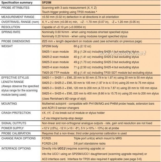
Speci?
cation summary (2)* NOTE: Dependant on CMM used and operating conditions.
Speci?
cation summary (3)Above data applies for test conditions as follows: Stylus length as stated above. Stylus velocity 480 mm/min (1.57 ft/min)
雷尼绍探针 雷尼绍探针

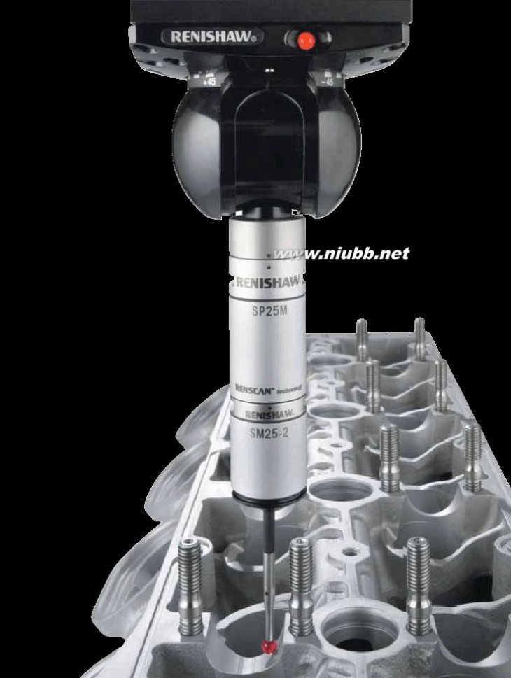
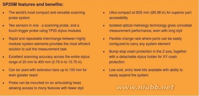
Probing systems forco-ordinate measuring machines SP25M compact scanningprobe systemSP25M scanning probeOnly 25 mm (0.98 in) in diameter, and with a range of modules for high performance scanning and touch-trigger probing, the SP25M is the world’s most compact and versatile scanning probe system.The SP25M is actually two sensors in one, enabling scanning and touch-trigger probing in a single probe system. SP25M gives highly accurate scanning performance with stylus lengths from 20 mm to 400 mm (0.79 in to
15.75 in) using M3 stylus range. In addition, the ability to carry Renishaw’s TP20 range of touch-trigger stylus modules means that the SP25M system enables best optimisation of the measurement solution to suit the application.The SP25M’s compact size and autojoint
mounting make it compatible with the
PH10M/MQ motorised probe heads and PH6M ? xed probe head. It can also be mounted on a multiwired extension bar of up to 100 mm
(3.94 in) length. Together, this combination
permits excellent reach and access to part
features.
A unique pivoting design achieves exceptional dynamic performance. Four scanning modules have been designed to optimise scanning
accuracy across a wide range of stylus lengths, avoiding most of the deterioration in performance seen in other types of scanning probe as stylus lengths increase.
SM25-4 module can scan very
deep features - shown here
with 400 mm (15.75 in) stylus
雷尼绍探针 雷尼绍探针


SP25M modular component
systemSP25M probe body
TM25-20SM25-1SM25-2SM25-3SM25-4
TP20 SH25-1
moduleSH25-2
SH25-3
SH25-4
EWL
20 mm to 50 mm
(0.79 in to 1.97 in)
EWL
50 mm to 105 mm
(1.97 in to 4.13 in)
EWL
120 mm to 200 mm
(4.72 in to 7.87 in)
EWL
220 mm to 400 mm
(8.66 in to 15.75 in)EWL - effective working length
雷尼绍探针 雷尼绍探针

Probing systems forco-ordinate measuring machines The SP25M system componentsThe SP25M probe body, which houses the isolated optical metrology transducer system, has autojoint compatibility with Renishaw’s PH10M/MQ, and PH6M probe heads, extension bars and ACR1/3 sensor changers.A range of four scanning modules SM25-1/-2/-3/-4 has been designed to provide optimised scanning performance over their speci? ed stylus length ranges. The SP25M’s innovative pivot-action motion, and the isolated optical metrology approach, mean that excellent accuracy is achieved over the entire stylus length range of 20 mm to 400 mm (0.79 in to 15.75 in).SH25-1/-2/-3/-4 stylus holders provide the ? exibility to have multiple stylus set-ups for each scanning module. The detachable stylus holder is located on the scanning module using a repeatable magnetic kinematic joint. It provides automatic stylus SP25M with changing capability and directly carries Renishaw’s M3 stylus range.100 mm (3.94 in) It is also possible to carry Renishaw’s TP20 range of touch-trigger probe modules extension bar
by using the TM25-20 adaptor module mounted on the SP25M probe body.between PH10 Rapid and repeatable interchange between all system elements allows easy head and probe selection of best probe solution. This can be automated to maximise productivity bodyby using the FCR25 ? exible change rack.
The SP25M can be connected directly to the UCC2 controller while a
daughtercard permits use with Renishaw’s UCC1 controller. The AC3 interface card allows integration with other controllers.
Using SP25M as a scanning probe:
The probe body has one of the four scanning modules attached (SM25-1/-2/-3/-4) which have matching stylus holders (SH25-1/-2/-3/-4). Each combination is optimised to maintain high accuracy and low contact forces over their dedicated range of effective stylus lengths. These are:
? SM25-1 + SH25-1 = 20 mm to 50 mm (0.79 in to 1.97 in) EWLSP25M scanningby use of 20 mm to 50 mm (0.78 in to 1.97 in) stylus
? SM25-2 + SH25-2 = 50 mm to 105 mm (1.97 in to 4.13 in) EWL
by use of 20 mm to 75 mm (0.78 in to 2.95 in) stylus
? SM25-3 + SH25-3 = 120 mm to 200 mm (4.72 in to 7.87 in) EWLby use of 20 mm to 100 mm (0.79 in to 3.94 in) stylus
? SM25-4 + SH25-4 = 220 mm to 400 mm (8.66 in to 15.75 in) EWLby use of 20 mm to 200 mm (0.79 in to 7.87 in) stylus
Using SP25M as a touch-trigger probe:
The probe body has the TM25-20 adaptor module attached, which directly carries any of Renishaw’s TP20 range of stylus modules:
? TP20 LF/SF/MF/EF
? TP20 EM1/EM2
? TP20-6W
Interfacing optionsSP25M taking
points with a TP20
SP25M can be integrated:module? directly using the UCC2 controller (requires scanning upgrade)
? by using Renishaw’s UCC1 controller (requires scanning upgrade) together with a SP25M/UCC1 daughtercard
? by using Renishaw’s AC3 interface card (ISA Bus) within the machine builder’s controller
雷尼绍探针 雷尼绍探针
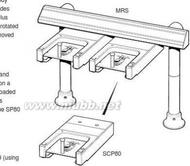
Automation using the FCR25 ?exible change rackThe full potential of the SP25M system is realised when the measurement routine is automated using the FCR25 ?exible change rack, a passive triple-port unit capable of storing any of the system elements. The FCR25 port stores the SM25-1/-2/-3/-4 and TM25-20 modules, but can instantly be con?gured to store the SH25-1/-2/-3/-4 stylus holders or TP20 modules by using the appropriate port adaptor insert: PA25-SH (for SH25-1/-2/-3/-4) or PA25-20 (for TP20 modules). The FCR25 mounts directly on Renishaw’s MRS modular rack system for multiple port solutions (3, 6, 9, 12, 15 etc). Alternatively, there are the FCR25-L3 (3 port) and FCR25-L6 (6 port) stand-alone rack variants that are ideal where machine space is limited.FCR25’s mounted to the MRS4-4Probe maintenanceCK200 (Renishaw part number A-1085-0016) is a specialised cleaning material, for the removal of contamination from the location faces of the magnetically retained kinematic couplings of the TP20, TP200 and SP25M probe systems. The frequency of cleaning should be determined according to the conditions of use.FCR2539.50 mm (1.56 in) 28 mm (1.10 in)PA25-20 PA25-SH 21.60 mm (0.85 in) 35 mm (1.38 in) nominal pitch 113.80 mm (4.48 in) 219.50 mm (8.64 in) 113.80 mm (4.48 in)74.5 mm (2.93 in)166 mm (6.57 in)166 mm (6.57 in)FCR25-L6 (6 port)FCR25-L6 (6 port)Scanning probes
雷尼绍探针 雷尼绍探针


Probing systems forco-ordinate measuring machines SP25M system component dimensionsdimensions mm (in)
雷尼绍探针 雷尼绍探针


* NOTE: Please refer to page 3-4 for TP20 speci? cation information.
SP25M’s modular design approach is the
key to high accuracy and user ? exibility
雷尼绍探针 雷尼绍探针

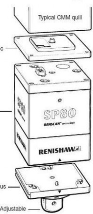
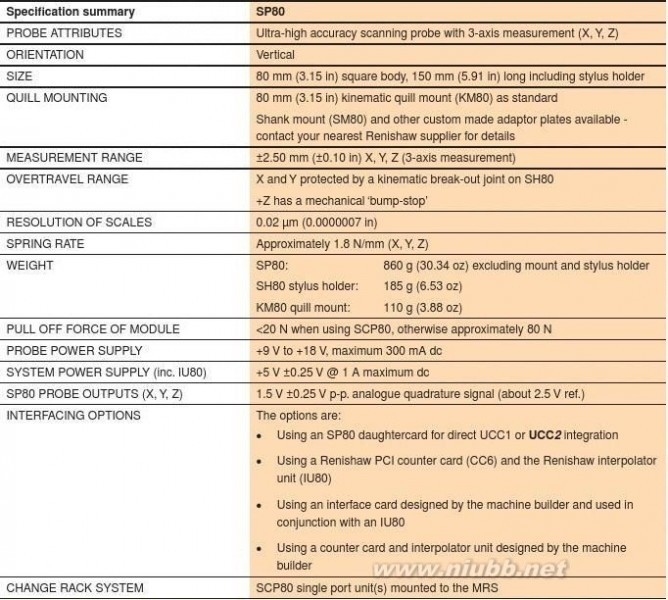
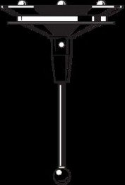
Probing systems forco-ordinate measuring machines SP80 - ultra-high accuracy scanning probeThe SP80 is a passive scanning probe using digital scale and readheads which enable a system resolution of 0.02 μm (0.00000079 in). This gives exceptional scanning performance, even with long styli.The SP80 can carry styli up to 800 mm (31.50 in) long and 500 g (17.64 oz) mass, including star con? gurations. Unbalanced star con? gurations do not require counterbalancing. Kinematic stylus holder changing allows for the repeatable re-location of the stylus, optimises stylus arrangements
for each feature, and overcomes the need for re-quali? cation.
The SP80 has a kinematic mount that provides a repeatable connection to the mating plate mounted on the quill (KM80), allowing the probe to be easily removed.Kinematic stylus holders provide crash protection in the XY plane, and a bump-stop prevents damage to the probe in the Z axis.NOTE: Please see the accessories page 13-4 for details of adaptor plates PHA80 and PHA3 which permit rapid interchange between SP80 and PH10MQ indexing motorised head.
Isolated optical metrology systemUsing an isolated optical metrology system, SP80 directly measures the de? ection of the whole mechanism, thus providing outstandingly accurate position sensing.The isolated optical metrology system can detect sources of variable error such as thermal and dynamic effects. In contrast, Electrical connection probes with displacement sensors mounted for readheadsto stacked axes suffer from latency under changing inertial loads, and cannot detect thermal growth in their mechanisms.
The readheads for each axis are ? xed to the body of the probe, and measure the de? ection in each direction. Any inter-axis errors caused by the arc motion of each pair of parallel-Readheads

acting springs are directly measured by the attached to sensor system. Isolated optical metrology probe body‘Moving cube’ systems have no moving wire connections. with scales
Shaded areas
Light is re? ected from indicate the the moving cube onto moving partsreadheadStylus mount
Isolated optical metrology
雷尼绍探针 雷尼绍探针


SP80 probe body
The sensor mechanism comprises an arrangement of three sets of parallel springs, one for each body axis, set in a cube - hence the body shape. The motion of the stylus is coupled to a ‘moving cube’ holding graduated re? ective scales - again one for each axis. The readheads are mounted on the wall of the probe and the light projected from them is re? ected from the moving scales. This method of motion detection does not require any form of moving wire connection.
Interface options
Interfacing the SP80 to a CMM can be achieved by:? Using an SP80 daughtercard for direct UCC1 or UCC2 integration
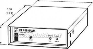
? Using a Renishaw PCI counter card (CC6) and the Renishaw interpolator unit IU80
? Using interface cards designed by the machine builder and used in conjunction with an IU80
?
Using a counter card and interpolator unit designed by the machine builder
The IU80 conditions the probe signal to provide a digital
industry standard EIA RS422 quadrature scale output, which can be accepted by CMM controllers.
Please contact Renishaw for full information on the methods detailed above.
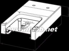
KM80 quill mount
This is ? xed to the quill and provides rapid and repeatable kinematic mounting of the SP80 body to the CMM.
SH80 stylus holder
mount attachment. For additional ?from the probe body to make the adjustment.
SCP80 stylus changing port
pull-off force is reduced to less than 20 N.
PHA3 and PHA80
The PHA3 and PHA80 adaptor plates enable rapid
PHA80) on the same CMM.
SP80 probe kit
quill mount
body
Two SCP80’s mounted on an MRS
雷尼绍探针 雷尼绍探针


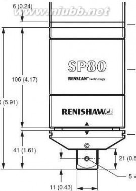
Probing systems forco-ordinate measuring machines SP80 / SH80dimensions in mm (in)View A
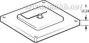
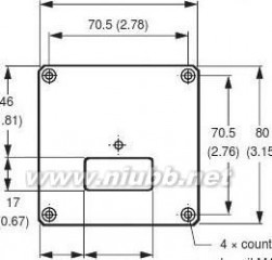
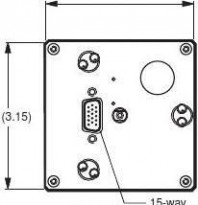
KM80SP80 bodySH80D-type plug
22 (0.87)
80 (3.15)
KM80(0.89)(1.38)attachment screws
SCP80IU80
140 (5.51)
34
(1.34)44
(5.04)
雷尼绍探针 雷尼绍探针


雷尼绍探针 雷尼绍探针

Probing systems for
co-ordinate measuring machines
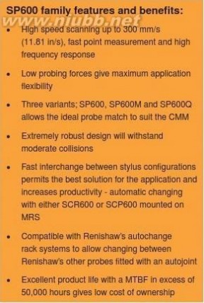
SP600, SP600M and SP600Q scanning probes
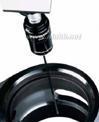
The SP600 (shank mounting), SP600M (multiwired autojoint mounting) and SP600Q (? xed in-quill mounting) are highly reliable analogue probes which are ideal for pro? le scanning and measurement on CMMs.
The SP600 family of scanning probes allow large amounts of data to be rapidly gathered for inspection and digitising purposes. Axis movement in each direction (X, Y and Z) is ±1 mm (±0.04 in) (in all orientation positions on a PH10) and stylus lengths up to 300 mm (11.81 in) can be used with the SH600 EXT stylus holder.
The SH600 provides overtravel protection, and allows rapid and repeatable interchange between stylus con? gurations. This can be automated by using the SCR600 stylus change rack or alternatively, individual SCP600 stylus change ports mounted to a MRS.
The probe design gives an excellent self centring ? gure of <5 μm (<0.0002 in); a measure of its ability to return to zero mechanically when not in contact with the part. This low ? gure, although irrelevant to the probe’s accuracy, enables the use of small de? ections and therefore low contact forces. The probe output always gives its precise position relative to the probe body.
Low mass, high structural stiffness and friction-free viscous damping give excellent dynamic performance characteristics.
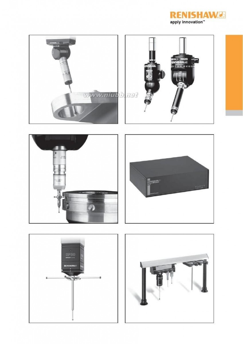
SP600 probe
The SP600 allows simple ? xed mounting via a Renishaw shank.
SP600M probe
The SP600M is mounted via an autojoint and can therefore be orientated by use with Renishaw’s PH10M or PH10MQ motorised probe heads. Rapid interchange with other
autojoint probes is possible by using a Renishaw ACR1 or ACR3 autochange rack system.


SP600Q probe
Compact in size, the SP600Q mounts directly onto the quill of the CMM. Together with the signi? cant reduction in size, the SP600Q provides a more cost-effective scanning option to CMM users with small working area requirements.
SP600
?50 mm (1.97 in)
1.50 mm (0.06 in)
SH600
12.50 mm (0.50 in)
1.50 mm (0.06 in)
SP600M
?50 mm (1.97 in)
1.5 mm (0.06 in)
SH600
12.5 mm (0.5 in)
SP600Q
60 mm square (2.40 in square)
1.50 mm (0.06 in)
SH600 12.5 mm EXT
(0.5 in)
雷尼绍探针 雷尼绍探针


SH600 STD / SH600 EXT stylus holders
The SH600 stylus holder provides overtravel protection, and allows rapid and repeatable interchange between stylus con? gurations. This can be automated by using the SCR600 stylus change rack or, alternatively,
individual SCP600 stylus change ports mounted on a MRS.
There are two variants, SH600 STD and SH600 EXT,
the difference being the stylus carrying capacity. The STD can carry up to 200 mm (7.87 in) and the EXT up
to 300 mm (11.81 in) long stylus.
SCR600 stylus change rack
The SCR600 is a passive stylus change rack for use with the SP600 probe family, and requires no electrical connections. It is protected from overtravel (in the probe entry direction) by a mechanism in the base which can be manually reset. It houses up to four SH600 stylus holders per rack and any number of racks can be used in a system.
SCP600 stylus change port
The SCP600 has passive operation like the SCR600 and mounts on the MRS. This allows ? exibility for users to con? gure multiple ports, to suit the application.
SH600
235 mm (9.25 in)
31.50 mm SCR600
(1.24 in)
?55 mm (?2.17 in)
MRS
SCP600 ports
mount to MRS
SCP600
雷尼绍探针 雷尼绍探针

Probing systems forco-ordinate measuring machines
雷尼绍探针 雷尼绍探针
雷尼绍探针 雷尼绍探针

Probing systems forco-ordinate measuring machines Manual probe heads

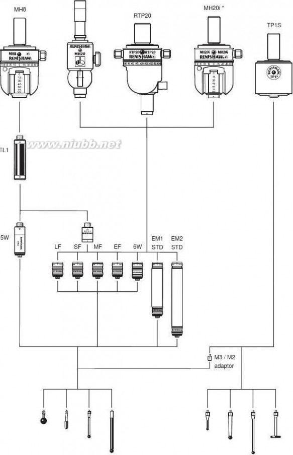
MIH or MIH-S
雷尼绍探针 雷尼绍探针


* PH1 is not compatible with TP200PH6M ?** PH6 has integral cable
? Compatible with multiwired systems
(TP7M, SP600M and SP25M)
? Specialised interface required
PEM25PEM1PEM2PEM25PEM1
M4 / M3 adaptorM3 thread styliM4 thread styli
雷尼绍探针 雷尼绍探针

Probing systems for
co-ordinate measuring machines * MH20/MH20i are covered in section 6MH20 *M2 thread styliM3 thread styli
雷尼绍探针 雷尼绍探针


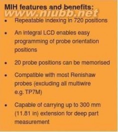
MIH manual indexingprobe head
The MIH is a versatile manual indexing probe head. It has programmable indexing positions using 7.5° increments and has an autojoint
probe mount for fast repeatable probe changing. These features can increase the productivity of a manual CMM.
MIH-S
MIH-S manual indexing probe head
The MIH-S is an enhanced version of the MIH which enables the feedback of positional status to the PC over an RS232 serial communication link, via the MIH-SI interface.This enables the CMM computer to:? Verify that the MIH-S has been moved to the correct position and locked into place.?
Identify the locked position of the MIH-S.
Measurement performance, functionality and dimensions are the same as for the MIH.
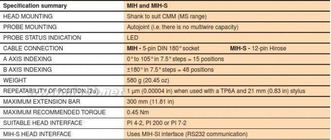
MIH / MIH-S

雷尼绍探针 雷尼绍探针

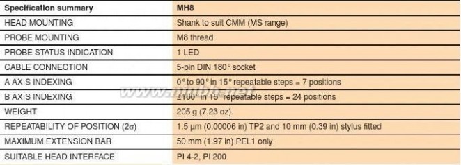
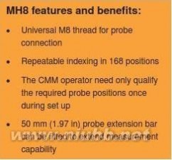
Probing systems forco-ordinate measuring machines MH8 manual indexing probe headThe MH8 is a compact, indexing probe head that is designed for use on small manual CMMs.It is compatible with TP20, TP6 and TP2 probes.
Please refer to page 5-3 for probe
compatibility information
)
n
i
2
7
?48 mm .
2
(
(1.89 in)m
m
9
6

雷尼绍探针 雷尼绍探针


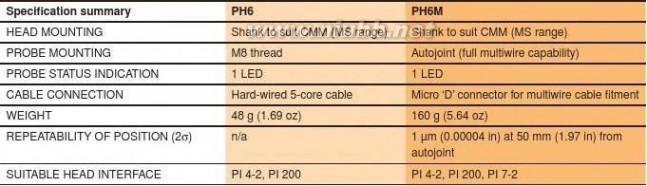
PH6 ? xed probe head
A compact, vertical probe head with a mount for M8 thread probes.

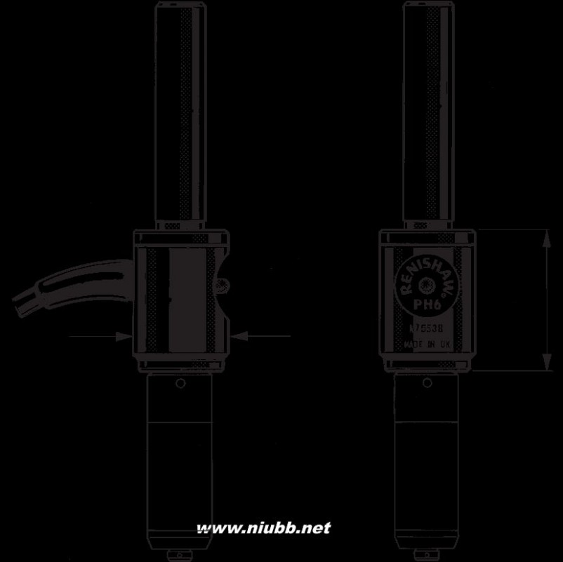
PH6M ? xed probe head
The PH6M is the multiwired version of the PH6 and is ?
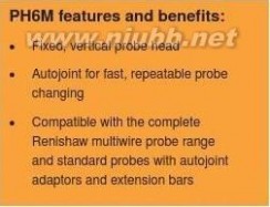
tted with an autojoint.
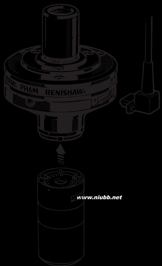
Please refer to page 5-1 and 5-2 for probe
compatibility information
雷尼绍探针 雷尼绍探针

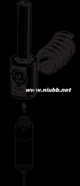
Probing systems forco-ordinate measuring machines PH1 manual articulating probe headA manual probe head with non-repeatable indexing in the B axis and ±115° rotation in the A axis. The probe is shank mounted to the CMM.

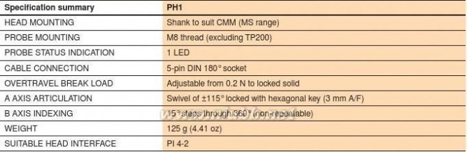

* Excluding shank and cable
雷尼绍探针 雷尼绍探针


RTP20 indexing head with integral TP20 touch-trigger probe
The RTP20 probe head allows the integral TP20 probe to be moved to 168 repeatable positions in 15-degree increments using both A and B axes, requiring a one-time quali? cation for each stylus tip position. This eliminates the need for costly time consuming requali? cation routines, ensuring fast throughput for part inspection.
Automated indexing of the RTP20 probe head is realised through an innovative process which uses the motion of a CMM to achieve ‘motorised’ head style operation.
An RTP20 integral TP20 probe mount optimises the working volume of the CMM and provides compatibility with all existing TP20 modules. Although modules can be changed manually, the RTP20 can be used with the MCR20 module change rack to allow fully automated module changing.
The RTP20 can be installed on new and existing measuring machines via a shank mounting, involving just the initial quali? cation of each measuring
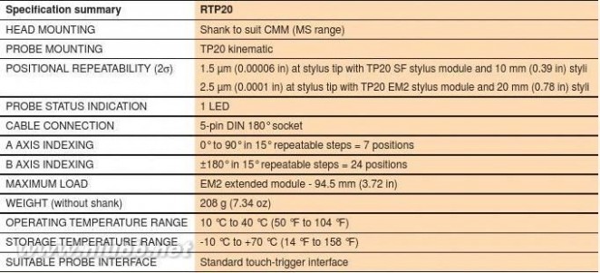
position and stylus combination.
?48 mm (1.89 in
47 mm (1.85 in)
86(3.
21 mm to 75 mm (0.83 in to 2.95 in)
A-axis 0° - 90°
5.7 mm (0.22 in)

Please refer to page 5-3 for probe compatibility
information

雷尼绍探针 雷尼绍探针

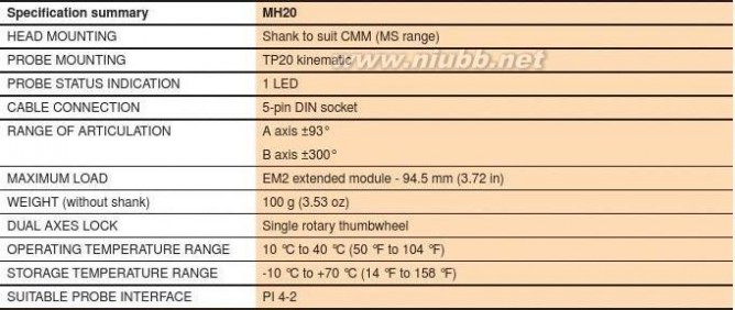
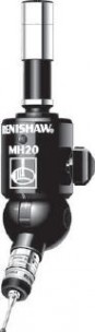
Probing systems forco-ordinate measuring machines MH20 manual articulating probe head with integral TP20 module mountThe MH20 is a compact probe head with fully adjustable orientation. The integral TP20 kinematic stylus module mount enables repeatable stylus module changing, without the need for re-quali? cation, providing head adjustment has not taken place. It is compatible with the full range of TP20 stylus modules, which comprises 5-way module versions with either length or trigger force options, plus a 6-way module. Multiple stylus con? gurations are easily interchanged allowing quick and easy access to work piece features.
The head is pre-mounted with a customer-speci? ed
shank to suit the CMM and features a red LED which
indicates probe status.

?31 mm (1.22 in)
)n
i
5
8
.
1
(
mm
7
4
Please refer to page 5-3 for probe axis ±93°
compatibility information
NOTE: The MH20 is compatible with the MSR1 module storage rack, but not with the MCR20 module change rack.
雷尼绍探针 雷尼绍探针


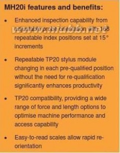
MH20i manual indexing probe head with integral TP20 module mount
The MH20i is a manual probe head with 2-axis adjustable indexing. Compact in design, it features an integral TP20 kinematic mount that enables repeatable stylus module changing without the need for re-quali? cation.The MH20i offers 168 repeatable index positions which are set at 15° increments to maximise ? exibility and productivity. Easy to read scales permit rapid re-orientation to pre-quali? ed positions, and its lock/unlock feature allows ease of positioning and eliminates unnecessary wear. It is compatible with the full range of TP20 stylus modules, which comprises 5-way module versions with either length or trigger force options, plus a 6-way module. Multiple stylus con? gurations are easily interchanged allowing quick and easy access to work piece features.
?48 mm (1.89 in)
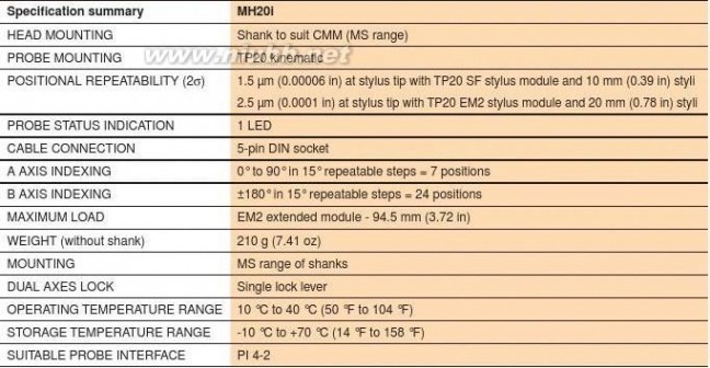
)
ni )
n6i4 .014( .m2( mm m73 16A axis 0° - 90°
5.7 mm (0.22 in)
B axis ±180°
Please refer to page 5-3 for probe
compatibility information
NOTE: The MH20i is compatible with the MSR1 module storage rack, but not with the MCR20 module change rack.
雷尼绍探针 雷尼绍探针

Probing systems for
co-ordinate measuring machines
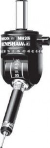
REVO?
The REVO? measuring head features
spherical air bearing technology in each of its two axes, driven by brushless motors linked to high-resolution encoders to provide fast, ultra-
high accuracy positioning.
REVO? system overview
RSP2RSP3
The system comprises the following elements:
? REVO? head
m
m?
RSP2 2D tip sensing probe and associated 05stylus holders and accessories
2m
m 0? RSP3 3D probe and associated
53accessories
m
m 0? UCC2 universal CMM controller
05? REVO? PCI interface card (for UCC2)3D probe
? SPA2 servo power ampli? er? Air ? lter unit
2D tip sensing
probes
REVO? - ‘tip sensing’ probe technology
? Enclosed laser directed onto a re? ector at the stylus tip.? The exact tip position is known because the re? ector
? The stylus touches the part and bends.and the stylus ball are close together.? The re? ector is displaced.
? Stylus wear is minimised by using a low scanning force.
? The altered return path of the laser is sensed by a PSD.
Re? ector
Return path to
PSD when stylus de? ected
PSD and
source
Stylus de? ection in Transmission and operation ~50 μmreturn path to PSD Stylus force ~5 g
when stylus NOT de? ected
雷尼绍探针 雷尼绍探针


REVO? features and bene? ts:
? Incorporates Renscan5? ? ve axis scanning
technology minimising CMM motion and the
associated CMM dynamic errors? Increased measuring speed, up to 500 mm/sec resulting in increased measurement throughput? Data collection rates up to 6,000 points per second
? In? nite positioning and ? ve axis motion reduces nonproductive transitions between features ? Stylus wear minimised by extremely low scanning forces
? In? nite positioning and ? ve axis motion aid access to dif? cult features? Rapid calibration with all positions inferred means more time measuring
? Maximum reach up to 500 mm with maintained effective working length
? Standard M2 styli for convenience
Probe
?
Probe and stylus changing capability allowing ? exibility and future probing technology compatibility
Stylus holder
Stylus
雷尼绍探针 雷尼绍探针

Probing systems forco-ordinate measuring machines Hardware integration? The UCC2 is fundamental to the REVO? system? SPA2 is a servo power ampli? er used to drive the head ? The UCC2 controller features Renscan5? scanning and CMMroutines particular to ? ve-axis motion and scanning? MCU1 is the multi-function hand control unit required for the systemUCC2
SPA2
MCU1
REVO?
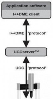
Software integration
? The Renishaw UCCserver? software application will provide the interface for REVO? control? UCCserver? is based on I++DME command protocol


雷尼绍探针 雷尼绍探针


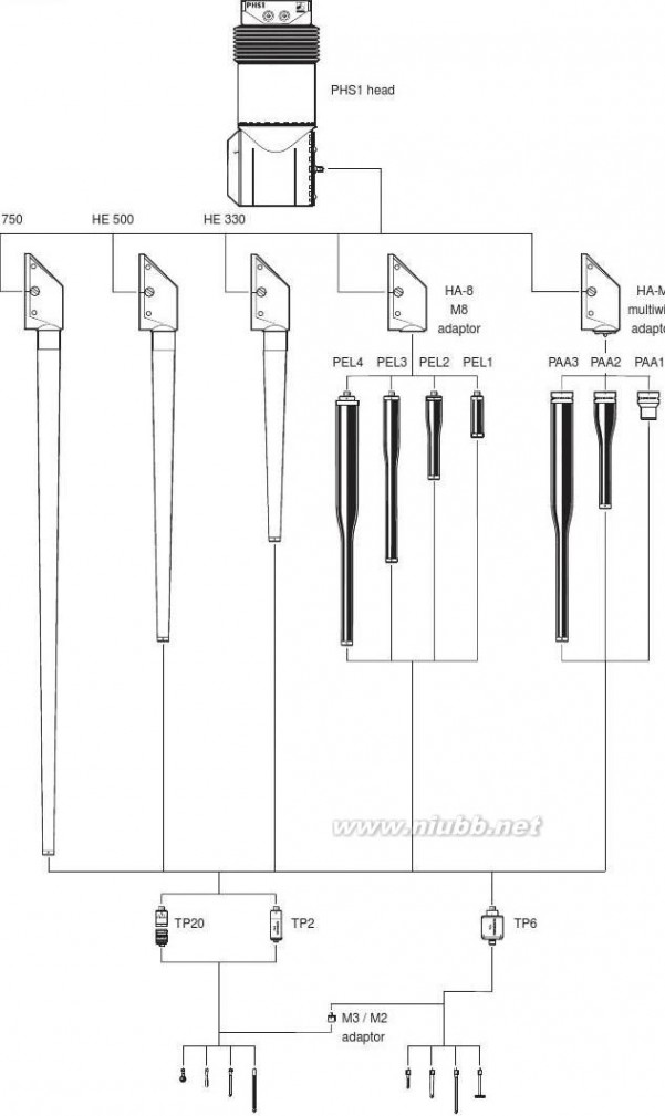
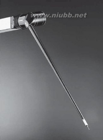
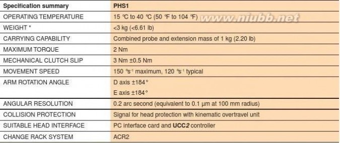
PHS1 motorised (servo type) probe head
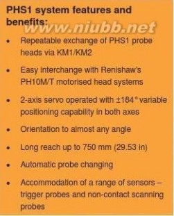
The Renishaw servo positioning head (PHS1) is a 2-axis motorised head with continuous KM2 kinematic mount
servo drive enabling the probe con? guration to be positioned at almost any angle.
The PHS1 has been designed to meet the demanding requirements of “body in white” measurement where ? ne angular positioning and long reach are needed.
KM1 kinematic mount
travel unit
PHS1 head
HE 330 / 500 / 750arm probe
HA-M arm probe
HA-8 arm probe
雷尼绍探针 雷尼绍探针

Probing systems forco-ordinate measuring machines M2 thread styliM3 thread styli
雷尼绍探针 雷尼绍探针


PHS1 head kit
The PHS1 head is not locked into position in the same manner as an indexing head. Instead, it is driven to approximately the required position and when a probing point is taken, the axes of the head latch simultaneously with the axes of the CMM to give accurate probe readings.
The PHS1 head is controlled directly via a PC interface card in the CMM controller, and requires full integration by the equipment supplier. Full information is given in the PHS1 programmers guide (PD-2100-9015).
A range of different probes can be ? tted and automatically exchanged. These include
touch-trigger probes and non-contact scanning probes.
Extra long extensions allow the Renishaw trigger probes to measure otherwise inaccessible features.A kinematic mount (KM1/KM2) allows quick ? xing of the head to the machine and fast changeover to other heads.
PH10M or PH10T heads can be ? tted (via a PHA1, PHA2 or a PHA3 probe head adaptor - details on request) instead of PHS1 in applications where existing parts need to be inspected without the need to re-write the programs for PHS1.The head is protected by a built-in overtravel protection unit that can be con? gured to stop the machine in the event of a collision.
An air supply to the head is recommended for axis motor cooling and optimum metrology
performance.
247 mm (9.72 in)
)
ni 49.3( mm 001?49.75 mm ?90 mm
雷尼绍探针 雷尼绍探针

Probing systems forco-ordinate measuring machines
The ACR2 autochange rack is an extension arm
changing system for the PHS1 servo positioning
head system.
It allows probe extensions or probe adaptors to
be exchanged to suit the probing task required
without manual intervention.
Its modular construction and simple operation
enable any number of racks to be positioned on
a pillar within the machine volume.
The rack is passive, all locking and unlocking of
adaptors and extensions is done by the motion
of the CMM.
ACR2* (including probe extension and kinematic joint)
雷尼绍探针 雷尼绍探针


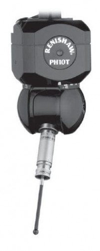
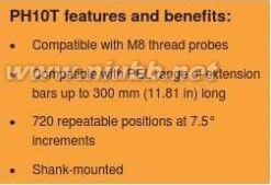
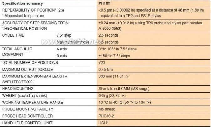
PH10T motorised indexing probe head
The PH10T is a motorised indexing head that mounts and re-orientates the probe. The PH10T can be repeatably orientated to any one of 720 positions.
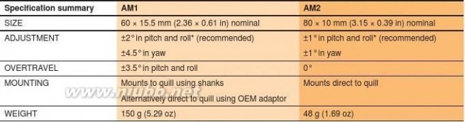
All M8 thread probes can be ? tted directly onto the mount of the PH10T. The PH10T is operated by the PHC10-2 and is compatible with other Renishaw M8 threaded products.The AM1 adjustment module permits the correction of the alignment of the probe head to the machine and is ? tted between the head and the shank.
62 mm (2.44 in)
)
ni 20.4( B axis
mm 201A axis
25 mm (0.98 in)

雷尼绍探针 雷尼绍探针

Probing systems forco-ordinate measuring machines ? Specialised interface requiredShankAM1PH10TPEL1PEL2PEL3PEL4
M3 / M2
adaptor
M3 thread styliM2 thread styli
雷尼绍探针 雷尼绍探针


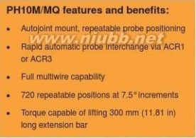
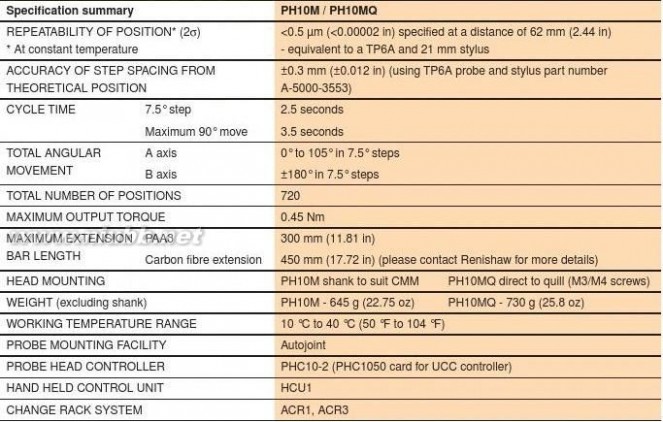
PH10M / PH10MQ motorised 10M
indexing probe heads
60 mm (2.36 in
The PH10M and PH10MQ are versatile motorised indexing heads that incorporate the Renishaw autojoint with multiwire capability. This allows PH10M/MQ heads to carry long
extension bars and sophisticated multiwired probes such as SP25M and TP7M. There are 720 repeatable positions, set at 7.5° increments to provide probe orientation.
117The highly repeatable, kinematic autojoint allows rapid (4.6
probe or extension bar changing without the need for re-B axis
quali? cation.
The PH10MQ is a variant that allows the motorised head to be attached directly to the quill with the ‘cube’ of the head A axis
inside the quill itself. This option provides a neater and 39 mm (1.54
shorter probe mount, with only the swivel protruding from the quill.
The AM1 and AM2 adjustment modules permit correction of alignment of the probe head to machine and are ? tted Multiwire
between the probe head and the shank/quill of the machine.
connector
60 mm(2.36 in)AM2 adjustment
squaremodule
34 mm10 mm(1.34 in)
(0.39 in)
80 mm
(3.15 in)(M4 × 25 mm
square
with AM2)
B axis73 mm(2.87 in)
A axis
39 mm (1.54) (to rollers)
雷尼绍探针 雷尼绍探针

Probing systems forco-ordinate measuring machines ? Specialised interface requiredNOTE: Please see the accessories page 13-4 for details of adaptor plates PHA3 and PHA80 which * When using a SP600M with a PH10MQ a PEM25 permit rapid interchange between PH10MQ and SP80 extension bar is required to achieve A = 97.5° or scanning probe.A = 105° in all B axis positionsShankAM1PH10MAM2
PH10MQ *
PAA3PAA2PAA1
PEL3PEL2PEM25 *PEM1PEM2PEM3PEM25 *??*
TP6TP7M ?
TP20TP200 ?
M4 / M3
adaptor
M3 / M2
adaptor
M2 thread styliM3 thread styliM4 thread styli
雷尼绍探针 雷尼绍探针


AM1 adjustment module for PH10T/M,
PH6M and MIH
The AM1 adjustment module has been designed for use with Lock/unlock screwthe PH6M and MIH manual probe heads and the PH10T/M
motorised probe heads. It provides quick and accurate
angular alignment of the probe head with the CMM’s axes Rolland/or the autochange rack.
In addition, the quick release mechanism allows the head to
be removed for storage and subsequently replaced without
further alignment. Built in overtravel protection decreases the
risk of head damage.
AM2 adjustment module for PH10MQ AM2PH10MQ motorised probe head is mounted directly to the
quill via the AM2 adjustment module.PH10MQ
M = Multiwire
Q = Quill

mounted* up to ±5.5° in pitch and roll is possible but this is at the expense of overtravel
雷尼绍探针 雷尼绍探针

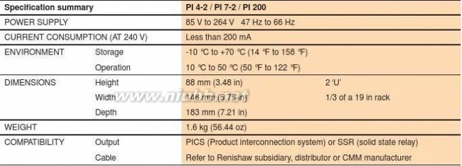
Probing systems forco-ordinate measuring machines PI 4-2 probe interfaceApplication - TP1, TP2, TP6, TP6A, TP20, SP25M (when using TP20) The PI 4-2 is the basic interface for standard touch-trigger probes that allows for a PICS (product interconnection system) or SSR (solid state relay) output, the supply voltage being automatically detected. The unit is usually free standing but can be rack mounted.PI 7-2 probe interface
Application - TP7M + TP2, TP6, TP6A, TP20
The PI 7-2 is a dual purpose interface designed
to process signals from the TP7M strain gauge
probe and standard touch-trigger probes.
Special autoselecting electronics within the
interface allow exchange of these probes without
any changes to the interface.
PI 200 probe interface
Application - TP200 + TP2, TP6, TP6A, TP20,
SP25M (when using TP20)
The PI 200 is a dual purpose interface designed
to process signals from the TP200 strain gauge
probe and standard touch-trigger probes.
Special autoselecting electronics within the
interface allow exchange of these probes without
any changes to the interface.

雷尼绍探针 雷尼绍探针


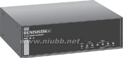
PHC10-2 head controller
The PHC10-2 head controller receives instructions from the CMM controller and controls the head functions and reports system status to the CMM:
a) Drives PH10 to position sent either from
the HCU1 or CMM.b) Checks and reports position.
c) Flags up errors e.g. failure to reach
position, obstruction before or after
locking etc. Probe triggering signals are routed through the controller to the probe

interface.
HCU1 hand held control unit
The HCU1 hand control and display unit is used with the PHC10-2 to drive the PH10 probe head position.
It is useful for setting up a component,
operator controlled inspection and teach-cycle programming. Features include two speed
action (jog and rapid move), 2-axis head display, transmit button for teach cycle, status and error LEDs.Features
a) Manual control of head movementsb) LCD dot matrix showing : Head position,
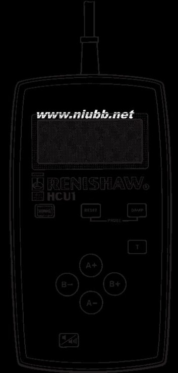
system status, and error analysis.
雷尼绍探针 雷尼绍探针

Probing systems forco-ordinate measuring machines IS1-2 interface selectorThe IS1-2 interface selector is a fully automatic system for The IS1-2 is also fully compatible with Renishaw’s ACR1 use on CMM installations requiring multiple sensor types and ACR3 probe exchange systems, the PH10M range (e.g. SP25M – scanning probe, TP7M – touch-trigger probe, of motorised heads and the PHS1 motorised servo head OTP6M – optical trigger probe, etc). The unit functions system using the Renishaw product interconnection system by identifying which probe has been ? tted to the probe (PICS).head and switches the probe signal / power lines to the appropriate interface.A set of four programming modules are supplied pre-installed within the IS1-2 unit which identify the probe The system comprises a standalone or rack-mountable in use. These are TP7M, SP600M, SP80 and SP25M interface selector. The IS1-2 has four separate channel modules. The remaining modules are supplied loose and outputs. These outputs allow any combination of the can be installed by the user. TP2, TP6, TP20, TP200 have following Renishaw probes to be integrated into one an integral identi? cation system and therefore do not require automated system:a module.? SP25MPlugging the required product module into the respective
? SP80channel selector socket ensures that the probe connections
are made to the correct IS1-2 output port.
? SP600Third party probes, that carry the female autojoint, will ? OTP6M*require speci? c identi? cation resistors to be ? tted within the ? TP7Mfemale autojoint. Special modules to permit the recognition
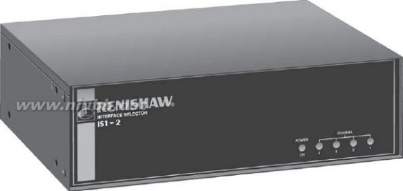
of these probes by the IS1-2 will also be required.
? TP2/TP6/TP20/TP200*
* These probes can be incorporated into a multiple
sensor system consisting of any one of the other probe systems speci? ed without the necessity to use an IS1-2 unit. Please contact Renishaw for further details.
雷尼绍探针 雷尼绍探针


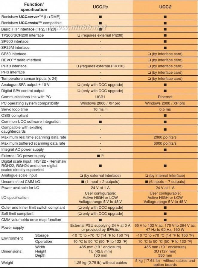
UCC2 universal CMM controller system
The UCC2 controller together with its associated products - the SPA2 or the SPAlite servo power ampli? ers and the MCU1 joystick, form a comprehensive CMM control system. This system is a sophisticated integrated motion controller that precisely controls CMM motion, including comprehensive scanning capabilities and automated probe calibration.
With UCC2 operating through an SPA2 or SPAlite, the CMM motion control is smooth, fast and accurate, permitting irregular contours to be easily followed thanks to the ‘move blending’ software.
The UCC2 has three levels of operating capability: touch-trigger probing, Renscan3? full 3-axis scanning capability which includes Renishaw’s patented RenscanDC?, and Renscan5? our new integrated 5-axis scanning system. All UCC2 controllers have I++DME capability enabled.Future hardware and software upgrades can be carried out easily, with function enhancements available by email or telephone support. Software enhancements are simply applied, as the control software is loaded at boot up.
Additional new products require only plug-in daughtercards.All new probes and heads will be available with a controller interface option that will also include any appropriate calibration or set-up software.
The UCC2 controller is housed in a standard rack-mountable enclosure and is connected to the host PC via a conventional Ethernet link. It does not contain user application software.
The SPA2 and SPAlite servo power ampli? ers are housed in standard rack-mountable enclosures and the cables necessary to connect them to the UCC2 are supplied as part of the kits.
The MCU1 machine control unit (joystick) is an
ergonomically designed unit suitable for both hand held or table based operation. It is supplied with a 5-metre cable as standard but other cable lengths or extensions can be used.
Scanning with UCC2
The UCC2 scanning capability provides a choice of scanning techniques:? Unknown part scanning, both 2D and 3D
?
Known part adaptive scanning, with sophisticated scanning routines that include :?
Cylinder scan (a helical scan path that can adapt to cones and spheres, as well as cylinders. It will also adapt to out-of-round and out-of-position parts). ? Gasket scan (a known path scan constructed from a series of lines and arcs).
? Grid scan (a 3D scan of a pre-de? ned area)?
Automatic ? nd centre:- Utilisation of a scanning probe to automatically ? nd the centre of a groove or conical hole
? Advanced data ? ltering
?
Advanced analogue probe calibration
UCC2 features and bene? ts:
? Capable of smooth, fast and accurate blending of CMM motion control
? Close integration between probing and the CMM optimises system measuring performance
? Closed-loop known part scanning includes cylinder, gasket and grid routines
?
Available with three levels of operating capability:
touch-trigger probing, Renscan3? and Renscan5?
?
Integrated control of all Renishaw standard touch-trigger and scanning probe systems plus stylus changing
? Full future product compatibility using plug-in daughtercards
?
I++ DME server application
RenscanDC? – the ultimate scanning performance from your CMM
Renishaw’s patented RenscanDC? system enables measurement at extremely high speeds, but with the accuracy of low speed measurement.
The traditional con? ict between accuracy and scanning
speed is resolved by RenscanDC’s feature based approach, which follows two steps:
1. Measure the feature at slow speed to establish an
accurate measurement. Repeat measurement at high speed to identify errors introduced at high speed.2. UCC2 automatically computes the dynamic error at
each point around the feature to derive a dynamic correction map. All subsequent parts can be measured at high speed and the application of dynamic corrections will provide low-speed accuracy at the fast measurement speeds.
雷尼绍探针 雷尼绍探针

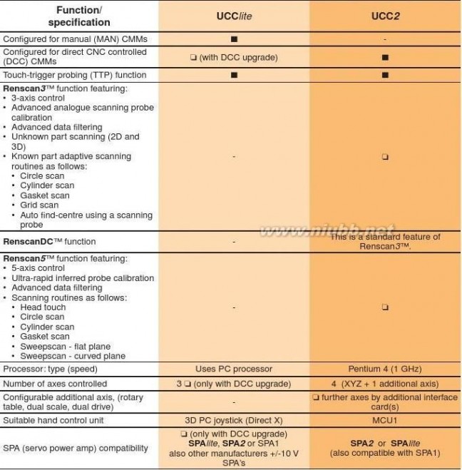
Probing systems forco-ordinate measuring machines UCClite controllerUCClite features and bene? ts:For applications needing only a basic TTP (touch-trigger probing) capability, there is UCClite, a lower speci? cation ? Low costcontroller con? gurable for use with either manual or DCC ? Entry level controllerCMMs and which uses simple USB1 connection.? Manual and dcc option? Touch-trigger only ? Remote PHC10 and TP200 I/F? USB1.1 link to PC? Digital tuning? Common software? Customer Microsoft compatible joystick
■ Standard speci? cation
? Available as a con? guration upgrade
雷尼绍探针 雷尼绍探针


■ Standard speci? cation
? Available as a con? guration upgrade
(1) Velocity loop is closed in the PC, nominally 10 ms (PC dependant)
(2) If used with SPAlite the external power supply is not required
雷尼绍探针 雷尼绍探针

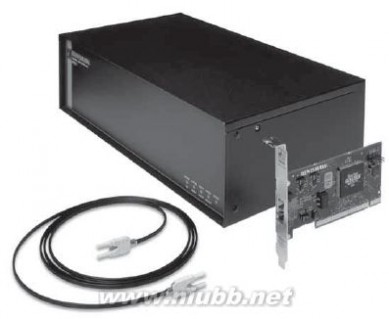
Probing systems forco-ordinate measuring machines UCC1 universal CMM controllerUCC1 features and bene? ts:The UCC1 is a sophisticated integrated motion controller that precisely controls CMM motion, probe calibration and ? Capable of smooth, fast and accurate blending of scanning capabilities. With UCC1, the CMM motion control CMM motion controlis smooth, fast and accurate, permitting irregular contours ? Closer integration between probing and the CMM to be easily followed thanks to the ‘move blending’ software.optimises system measuring performanceThe UCC1 has three levels of operating capability: touch-? Closed-loop known part scanning includes cylinder, trigger probing, full scanning and UCCserver? (I++DME) gasket and grid routinescapability.? Available with three levels of operating capability: Future hardware and software upgrades can be carried out touch-trigger probing, full scanning and easily, with function enhancements available by email or UCCserver? (I++DME) capabilitytelephone. Software enhancements are simply applied, as ? Integrated control of all Renishaw standard touch-the control software is loaded at boot up. Additional new trigger probe systems and stylus changingproducts require only plug-in daughtercards.
? Full future product compatibility using plug-in
All new probes and heads will be available with a controller daughtercardsinterface option that will also include any appropriate calibration or set-up software.
The UCC1 controller is housed in a standard rack-mountable enclosure with a twin optical ? bre link to a
simple PC plug-in card. It does not contain user application software.
Scanning with UCC1
The UCC1 scanning capability provides a choice of scanning techniques:
? Known part adaptive scanning, with sophisticated scanning routines that include :
? Cylinder scan (a helical scan path that can adapt to cones and spheres, as well as cylinders. It will also adapt to out-of-round and out-of-position parts). ? Gasket scan (a known path scan constructed from a series of lines and arcs).
? Grid scan (a 3D scan of a pre-de? ned area)? Advanced data ? ltering
? Advanced analogue probe calibration
? Automatic ? nd centre:- Utilisation of a scanning probe to automatically ? nd the centre of a groove or conical hole
雷尼绍探针 雷尼绍探针


UCC1 technical speci? cation
?
19” 3U standard rack-mountable enclosure with 7 expansion slots for option cards? Simple PCI plug-in card for the front-end computer
?
10 Mb capacity high-speed optical data link between
UCC1 and front-end PC
? 3-axis control?
Scale inputs:- Renishaw RGH22, RGH24, RGH41 and
other digital scales directly supported, analogue scales supported via an external interface
?
Uncommitted Binary I/O:- 6 inputs and 7 outputs available as standard
? Comprehensive joystick interface
?
TP20, TP200/SCR200 and SP600 interfaces available as standard?
Compatibility with other Renishaw probes, such as SP25M and SP80 by use of daughter card
? Internal error-map?
The following option cards are available:-? PH10/50 motorised head interface? PICS/RS232 auxiliary product interface ? SP25M scanning probe interface? SP80 scanning probe interface? Temperature sensor inputs (24)
?
Joystick interface (for 3rd party analogue joysticks)
Operational
? Touch-trigger? Scanning?
UCCserver
? (I++DME)
雷尼绍探针 雷尼绍探针

Probing systems for
co-ordinate measuring machines
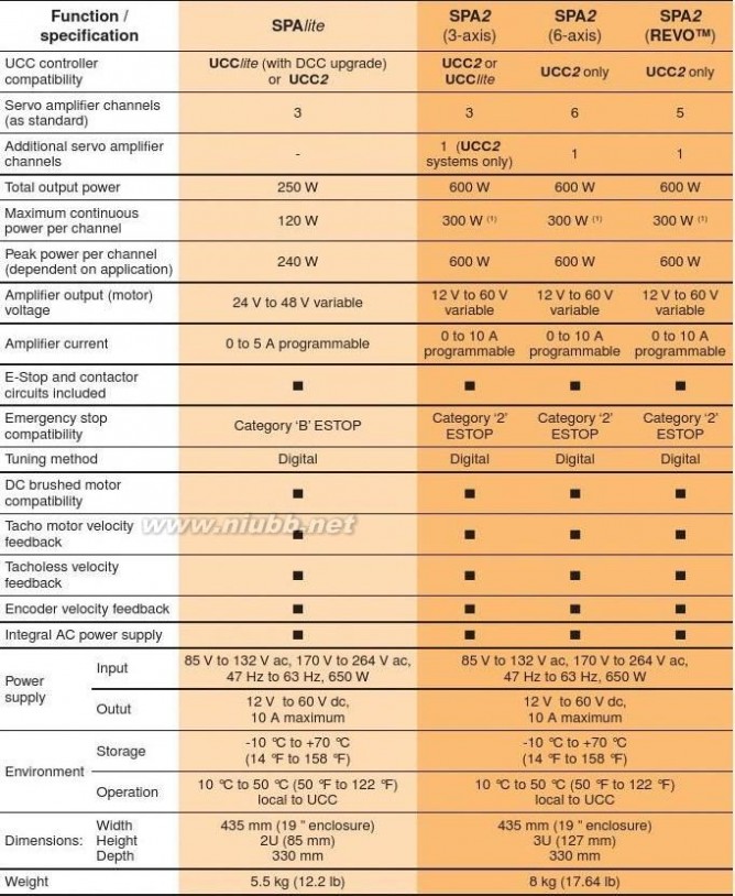
SPA2 servo power ampli? er for UCC2
The SPA2 is available as a 3 or 6 channel digital servo power ampli? er with an integral power supply. An additional axis can simply be added to either model to convert it into a 4 or 7 channel SPA. The design has been optimised to
work with the UCC2 or UCClite CMM controllers and all the necessary interconnection cables are provided in the kits. When the SPA2 is used with the UCC2 controller and MCU1 joystick, you have an ideal retro? t package. For each ampli? er channel, there are individual software controls for all the tuning parameters including offset, gain, integral and proportional settings. The motor and tacho polarities can also be inverted by software.
The power supply can be set to provide a voltage output from 12 V to 60 V. The maximum total output power is 600 W and each channel can deliver 10 A peak or 5 A continuous.
As well as the servo power ampli? ers, the unit contains all the relays to control the motor engaging process. It also contains all the necessary hardware to implement a category ‘2’ emergency stop system.
With mounting brackets, the system may be housed in a

3U high × 19 in wide, rack mountable enclosure.
SPAlite servo power ampli? er
SPAlite is a lower powered 3-axis servo power ampli? er unit suitable for smaller CMMs typically up to 1 m3 volume.
SPA2 and SPAlite both feature digital tuning.
SPA2 features and bene? ts:
? Full digital tuning capability
? Linear, DC brushed and brushless motor capability? Tacho, tacholess and encoder motor feedback? Integral power supply
?
Up to 7 servo ampli? er channels
SPAlite features and bene? ts:
? Low cost
? Compatible with UCClite and UCC2 ?
Tacho, tacholess and encoder motor velocity control
? 3-axes? Digital tuning
雷尼绍探针 雷尼绍探针


■ Standard speci? cation
? Available as a con? guration upgrade
(1) Peak power of 600 W can be drawn for a maximum of 50 seconds
雷尼绍探针 雷尼绍探针

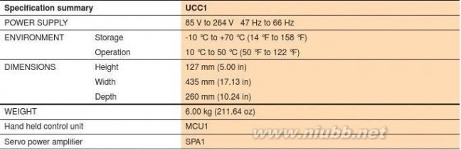
Probing systems forco-ordinate measuring machines SPA1 servo power ampli? er for UCC1The SPA1 is a 3-channel servo power ampli? er with an integral power supply.The design has been optimised to work with the UCC1 CMM controller and all the necessary interconnection cables are provided in the kit. When the SPA1 is used together with the UCC1 controller and MCU1 joystick, you have an ideal retro? t package. For each ampli? er channel there are individual controls for offset, gain, derivative and proportional settings.
The power supply can be set to provide either
24 V or 48 V, the maximum total output current
is 10 A and each individual channel can deliver
10 A peak (for 2 seconds) or 7 A continuous.
There are selectable chokes ? tted to
accommodate low inductance motors.
As well as the servo power ampli? ers, the unit
incorporates a category ‘B’ Emergency Stop
system and the necessary relays to control the
motor engaging process.
The system is housed in a 3U high x 19 in wide,
rack mountable enclosure.
A SPA1 service pack is available, it consists of
a full set of connectors and backshells, a set of
potentiometers to assist the tuning process are


also included.
雷尼绍探针 雷尼绍探针


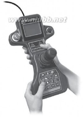
MCU1 multi-functional hand control unit
The MCU1 is a multi-functional hand control unit that provides complete CMM control.
Designed for use with the UCC range of controllers, the MCU1 is housed in an ergonomically styled enclosure
that allows for hand held (suitable for both right and left handed operators) or table mounted operation.
The MCU1 is supplied as standard with a 5 metre cable, other cable lengths and/or extensions can be used.A large LCD screen gives status information and allows for interaction with the metrology program.
A MCU1 docking port is also available that allows the MCU1 to be stored on the side of a cabinet, CMM bed
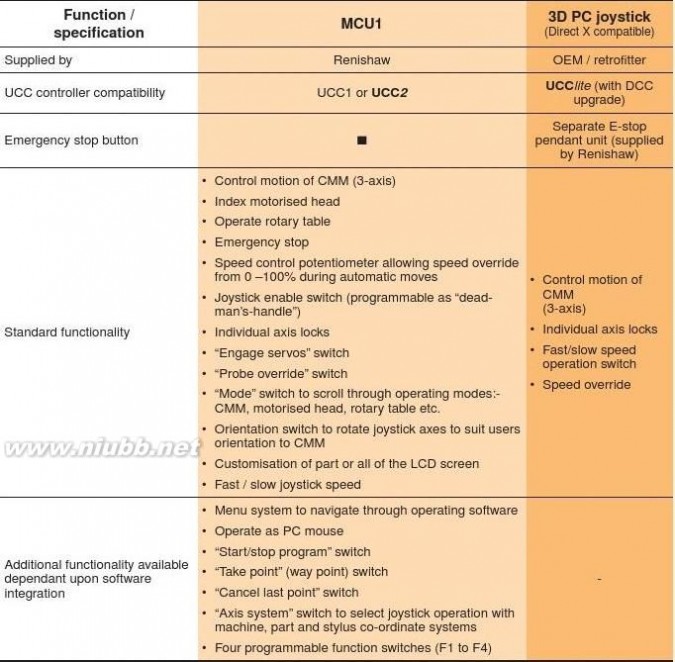
or any other non-horizontal surface.
■ Standard speci? cation
雷尼绍探针 雷尼绍探针

Probing systems forco-ordinate measuring machines

Autochange systemThe autojointThe essential feature of Renishaw’s autochange systems is the autojoint itself. This is a highly repeatable kinematic joint, one half of which is attached to the probe head, the other is attached to an adaptor, extension bar or probe.Head/extension barLocking and unlocking the autojoint is achieved either manually, using an autojoint key or, Clamping automatically, using either the ACR1 or ACR3 mechanismautochange rack systems. In all cases, the connection repeatability eliminates the need for Kinematic probe requali? cation after each probe exchange.king/unlocking screwlocationIn addition to mechanical repeatability, the
autojoint carries thirteen electrical connections,
known as the Renishaw multiwire. These carry Electrical simple two wire TTP signals and also the more contactsdemanding signals from analogue scanning and
non-contact laser probes, providing the bene? t of
the complete Renishaw range.PAA1 adaptor
雷尼绍探针 雷尼绍探针


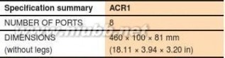
ACR1 autochange rack
The ACR1 system is a fully integrated 8-port probe autochange system. It is mounted within the machine’s working envelope and allows probe/stylus combinations to be exchanged automatically from heads and extension bars, without the need for re-quali? cation.g
el )ACR1 has been revised to allow on-site
ni con? guration of the ports to accommodate 31.extra large probes such as optical sensors.m
21(g
It is also possible to use the ACR3 to em L4m0m autochange between the head and probe 2803(please see page 10-3).
htiw )For further assistance in choosing niyour system, please see H-1000-3032/
g
5e0L.H-1000-3033 autochange systems brochure.
71( mm NOTE: This system can be mounted both 334horizontally (as shown) or vertically. To mount vertically a vertical mounting kit is required ACR1 autochange rack(not supplied).
with adjustable base

The example shows the ? exibility which substantially increases the usefulness and effectiveness of the CMM.
Legs are constructed from 104 mm and
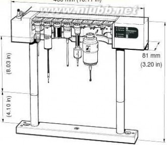
204 mm (4.09 in and 8.03 in) modules.

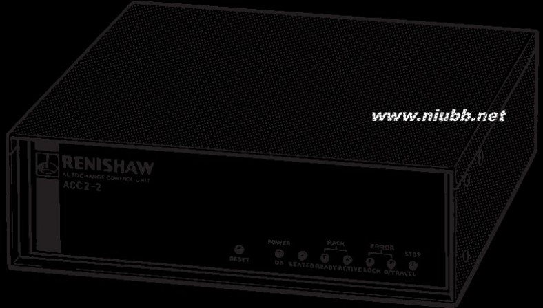
ACC2-2 autochange controller for
ACR1
The ACC2-2 is the RS232 only version of the ACR1 autochange controller. For IEEE support please contact Renishaw.
雷尼绍探针 雷尼绍探针


Probing systems forco-ordinate measuring machines

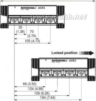
ACR3 autochange rackRenishaw’s ACR3 autochange rack is a passive, 4-port probe changing system. It is ? tted to Renishaw’s modular rack system (MRS) which has been designed to provide a platform for Renishaw’s latest range of stylus and probe changing racks.The ACR3 uses the motion of the CMM to lock/unlock the autojoint between the probe head and the probe/extension. ACR3 is therefore a passive mechanical design without the need for rack motors or electrical interfacing.Integration with the metrology software ACR3 4-port system
is required (please consult your machine mounted to MRSsupplier for details).
All Renishaw probes and extension bars ? tted with the autojoint can be carried. Some third party probes that incorporate the Renishaw autojoint can also be used with ACR3. (Please consult your machine supplier for details).For additional ? exibility, two four port units can be linked to provide an eight port system.The total swept volume along the MRS during a change cycle is:
1 × ACR3 275 mm (10.83 in)2 × ACR3s linked 460 mm (18.11 in)ACR3 and two SCP600’s The extruded rail of the MRS is available in mounted to MRSdifferent lengths 400 mm/600 mm/1000 mm (15.8 in/23.6 in/39.4 in) to suit the number and combination of changer requirements. In addition the height of the MRS can easily be upgraded after installation allowing Unlocked positiondimensions in mm (in)further ? exibility to meet application needs. For more details on the MRS please refer to section 13-1. Additionally an ACR3 data sheet H-1000-2024, and autochange systems brochure H-1000-3032/H-1000-3033 are available.
4-port ACR3 operating envelope
雷尼绍探针 雷尼绍探针


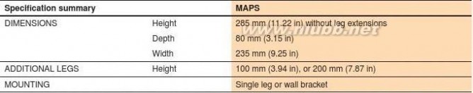
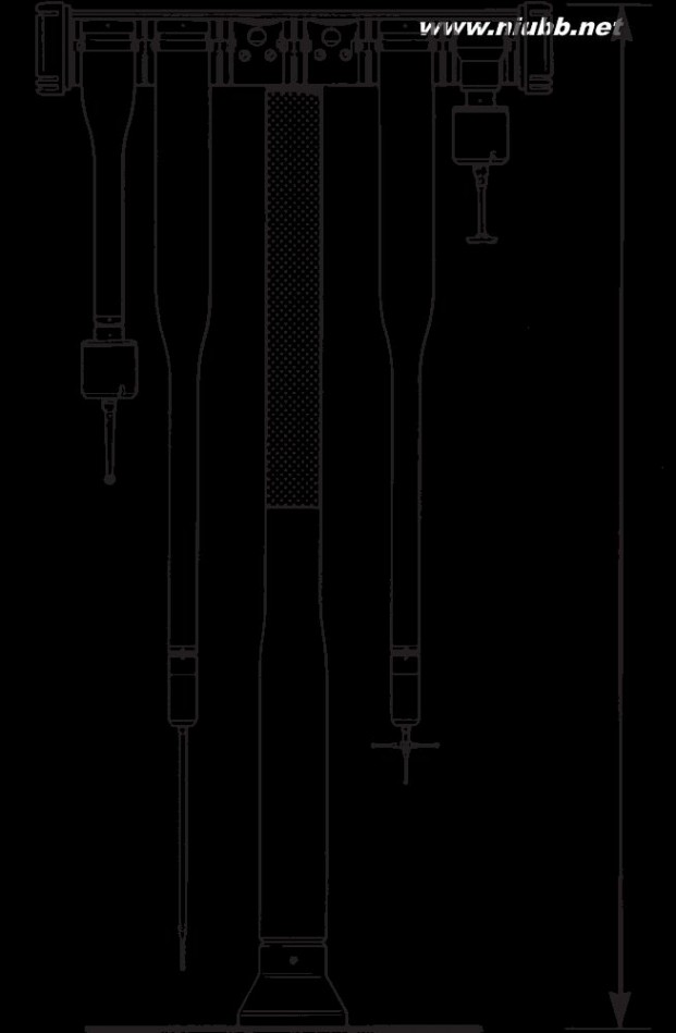
MAPS manual autojoint 235 mm (9.25 in)
probe stand
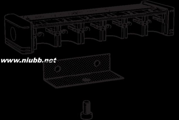
Renishaw’s manual autojoint probe stand (MAPS) is a low cost storage rack capable of holding up to six combinations of autojointed probes, extension bars and accessories.The stand can be mounted directly onto the table of a CMM (or any suitable surface) using the leg mount.
80 mm Standard ACR1 autochange rack legs
m
(3.15 in)
(100 mm and 200 mm long) are compatible in)
with this stand and can be stacked to
accommodate longer probe extensions with longer stylus extensions.
As an alternative to the leg mount, a wall mounting bracket is available to enable the stand to be mounted to a cabinet, wall or any vertical surface.
雷尼绍探针 雷尼绍探针

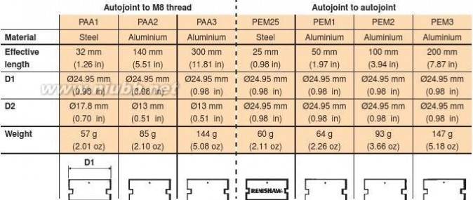
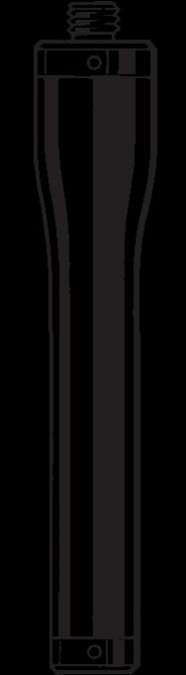
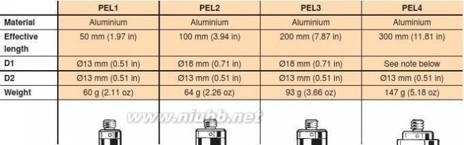
Probing systems forco-ordinate measuring machines Extension bars - autojoint type


NOTE: Check suitability in sections 5/6 for manual head systems and sections 7/8 for motorised head systems.
PEM extension bars are designed to be used with the TP7M multiwired probe, the SP600M and SP25M scanning probes, as well as other touch-trigger probes using an adaptor.
雷尼绍探针 雷尼绍探针


Extension bars - M8 to M8 type


PK1 knuckle joint
The PK1 can be used with all heads except
MH20 and MH20i.
NOTE:
D1 (a) ?24.95 mm (0.98 in)
D1 (b) ?17.8 mm (0.70 in)
D1 (a)D1 (b)
80 mm (3.15 in)
PEL4
雷尼绍探针 雷尼绍探针
Probing systems for
co-ordinate measuring machines
Shanks (except PH6 and MH20)
Shanks are used to mount the probe head to the quill of the machine.
All dimensions in mm (in)
The shanks detailed below are suitable for all Renishaw manual and motorised probe heads (except PH6 and MH20), as well as the TP1 probe. The correct shank must be chosen to suit the mounting facility of your CMM.Standard base diameter is 41.35 mm - 41.45 mm (1.62 in - 1.63 in).
?20.0 (0.79)
M5 × 0.8 mm
?24.984 to 1/4 in BSF × 26TPI
?9.500 to ?7.0 (0.28)
24.989
0)
9.512 ?9.497 to
0(0.9836 to ?10.008
)
9380 )
.7..83.(0.3740 to 9.524 020.9838)
6405(.410.01341)
(0.3745)
406...31((0.3940512((0.3739 to 0.3750)0.3942MS1
MS2
MS3
MS4?18.0 (0.71)
1/4 in BSF × 26TPI
CirclipWasher?7.0 (0.28)
)
Bush
?7.0 (0.28)
05.53.83(?24.995 to
7)
49?10.008 to ?13.997 to ?15.983 to 25.000 .75.41 )
(10.013 0814.003 15.994 (0.9841 to )
(0.3940 to .0508..1(0.5511 to (0.6293 to 0.9843)
453.(0.3942)0.5513)
31(0.6297)
MS5
11.0MS6
MS7
MS8
(0.43)
?7 mm (0.28 in)
?7.0 (0.28)
?13.97 mm (0.55 in)
?10.0?26.0 (1.02)
(0.39)
?13.990 to M10 × 1.5 mm
13.996
?13.960 to
)
)
08mn(0.5508 to )
.i0813.970 59m .. 20?14.996 to 0034.(.60.5510)
62((0.5496 to )
0214.998 6.62(.0.5500)
0 )
6.0521(0.5904 to .(78.410.5905)
(MS9
13.0MS10
19.0MS11
MS12
?16.0(0.51)
(0.75)
(0.63)
?7.0 (0.28)?7.0 (0.28)
?11.993 to 11.998 (0.4722 to ?16.0 (0.63)
?11.989 to ?13.997 to 0.4724)
)
12.000 )
14.003 ?19.991 to 0707
).09.(0.4720 to .9(0.5511 to 06?5.00..515103.
)
0820.000 (.0.4724)(0.5513)
62(0.20)
(59.20(0.7870 to (0.7874)
15.0 (0.59)
MS13
MS14
MS15
MS17
雷尼绍探针 雷尼绍探针


Shanks (for PH6 and MH20 only)
The shanks detailed on this page are suitable for the PH6 and MH20 manual All dimensions in mm (in)
probe heads only.
Standard base diameter is 18.9 mm - 19.1 mm (0.74 in - 0.75 in) unless otherwise stated.
?9.500 to ?9.500 to 9.512 9.512 (0.3740 to
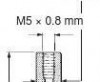
?9.500 to 9.512 ?7.0(0.3740 to (0.28)
0.3745)
(0.3740 to 1/4 in BSF
Circlip0.3745)WasherBush
4)
?10.008 to )
)
.07935.59.710.013 3721.( )
.5.4141(((0.3940 to 08.?15.983 to 53.0.3942)
31(15.994 (0.6293 to 0.6297)
1/4 in BSF1/4 in BSF1/4 in BSF1/4 in BSF1/4 in BSFMS1/T
MS3/T
MS5/T
MS7/T
?18.0 (0.71)
)
)
666)
.330.(44 58( 990?13.990 to 13.996 ...203 9o0t1?5.30 93(0.21)
89.0)
(n 0i 5030..35)
2n ?11.998 ( imo t7to 11.993 m 09. 591)
9((0.4724 to 8 6.40.4.2010.4722)
?5.(60.21(?40.0(1.58)
1/4 in BSF?30.01/4 in BSF1/4 in BSF1/4 in BSFMS8/T
(1.18)
MS9/T
MS11/T
MS18/T
雷尼绍探针 雷尼绍探针

Probing systems forco-ordinate measuring machines MRS modular rack systemRenishaw’s modular rack system (MRS) allows customisation of probe and stylus changing racks to optimise CMM functionality.The MRS is a modular system designed to provide a platform for Renishaw probe and stylus changing racks. It comprises a rail and two leg assemblies, and is available in three different standard rail lengths, 400 mm, 600 mm and 1000 mm (15.75 in, 23.62 in and 39.37 in) to suit a number of changer requirements.The MRS rail can also be placed at different heights from the CMM’s bed by using multiple
MRS legs to allow the required clearance for long styli and extension bars.
The standard interconnecting MRS legs
supplied (4 per kit) are each 125 mm (4.92 in) long. A maximum recommended leg length of 500 mm (19.69 in) can be achieved by purchasing additional legs. These are
available in either 62.5 mm or 125 mm (2.46 in or 4.92 in) lengths. The rack is mounted on the CMM bed via two MRS feet attached to the legs.
Where heavier rack system con? gurations are to be used e.g. multiple SCP80s mounted to a 1000 mm (39.37 in) rail length, the MRS system can be upgraded by using the optional heavy duty legs which are ?60 mm × 350 mm long (?2.36 in × 13.78 in long). These legs mount beneath the standard legs/feet and are attached to the CMM bed.
The MRS is compatible with the following Renishaw change rack systems:
? FCR25 (? exible change rack for SP25M)? SCP80 (stylus change port for SP80)? SCP600 (stylus change port for SP600/SP600M/SP600Q)
?
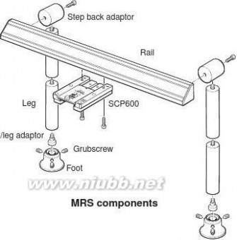
ACR3 (autochange rack)MRS with SCP600M8 screw
雷尼绍探针 雷尼绍探针


MRS heavy duty legs
?60 mm (2.36 in)
Where an MRS installation has
4numerous SCP80s containing heavy stylus arrangements, or vertical stylus
5arrangements exceeding 190 mm (7.48 in), it is recommended that the optional MRS heavy duty leg kits are used to provide additional rigidity/height.
These kits are purchased separately to match the number of legs used in the MRS installation. The heavy duty leg kit stands )
ni 330 mm (12.99 in) tall and is positioned 04.between the CMM table and the standard 21(MRS leg assembly.
mm 51NOTE: The MRS heavy-duty leg kit part 3number is A-4192-0020 and comprises one heavy duty leg assembly. Therefore, two kits are required for a typical MRS installation.MRS heavy duty leg kit1. Heavy duty leg
2. Double-ended threaded stud *3. Footplate
Standard MRS kit parts4. Standard MRS leg15 mm5. Leg to foot adaptor(0.59 in)
6. M10 bolt7. MRS foot*

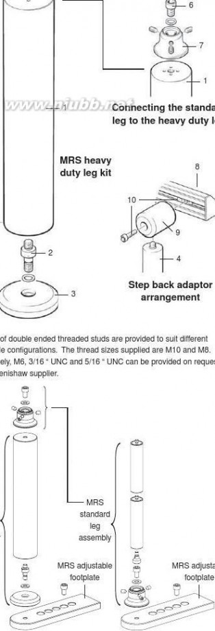
8. MRS rail
9. Step back adaptor10. Tee nut and bolt
MRS adjustable footplates
By using the optional MRS adjustable
footplates, the MRS rail can also be placed at different positions on the CMM’s table thereby ensuring that a maximised working volume can be achieved. The MRS adjustable footplates can be used with the MRS
MRS standard leg and the MRS heavy duty leg heavy arrangements. The range of adjustment is via four boltholes in steps: 25 mm/50 mm/75 mm/100 mm (0.98 in/1.97 in/2.95 in/3.94 in).
NOTE: The MRS adjustable footplates kit part number is A-4192-0702 and comprises two
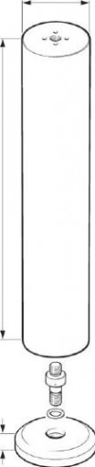
footplates.
MRS adjustable footplate arrangements with standard and
heavy duty MRS leg arrangements
雷尼绍探针 雷尼绍探针

Probing systems forco-ordinate measuring machines
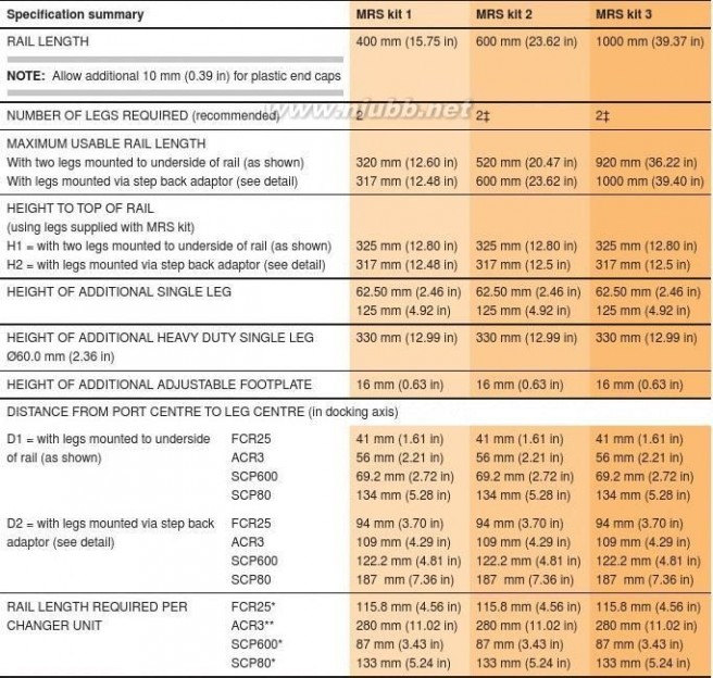
Detail showing alternative leg arrangement using step back adaptorD1H2docking H1axis2
SCP80
SCP600FCR25ACR3
* Includes 2 mm (0.08 in) extra ** Includes 5 mm (0.20 in) extra ? Centre leg may be required in certain allowance per unit allowance per unit applications
雷尼绍探针 雷尼绍探针


PHA3 and PHA80
The PHA3 and PHA80 adaptor plates enable rapid However, the PHA3 is supplied in two pieces - the PH10MQ interchange between PH10MQ (using PHA3) and SP80 is ? rst mounted to the lower hollow piece making a sub-(using PHA80) on the same CMM.assembly, then the electrical connectors are attached before The CMM quill must ? rst be ? tted with a KM1 or KM2 bolting this sub-assembly to the bottom face of the upper (kinematic mounting plate) as appropriate, to which the piece which has the KM1/2 joint on its top face.PHA3/PHA80 mounts via a repeatable kinematic joint It is possible to incorporate the IS1-2 interface selector unit featuring quick lock/unlock by simply turning a key. The into the system interconnection scheme.PH10MQ has to be pre-mounted on the PHA3 and similarly the SP80 to the PHA80. The general mechanical scheme is shown below.
The PHA80 is a single-piece item with the KM1/2 joint on its top face, and a direct mount to the top of the SP80 probe body on its bottom face. Therefore The KM80 is not required.


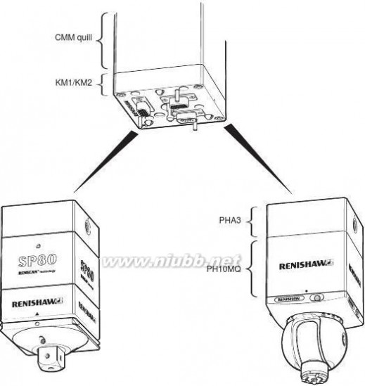
PHA80SP80 probe body and SH80
stylus holder
PHA3 and PHA80 enable rapid interchange between
SP80 and PH10MQ on the same CMM
Cleaning kit - CK200
CK200 (Renishaw part number A-1085-0016) is a The frequency of cleaning should be determined according specialised cleaning material supplied for the removal of to the conditions of use.contamination from the location faces of the magnetically retained kinematic couplings of the TP20, TP200 and SP25M probe systems.
雷尼绍探针 雷尼绍探针

Probing systems for
co-ordinate measuring machines
UDS universal datum sphere
The Renishaw universal datum sphere complements the performance of manual and fully automated CMMs.
Quick and easy adjustment to set ball stem over a wide range of probe quali? cation angles. This enables quali? cation above, centrally and below the ball. The hand adjustable pivot joint enables stem rotation through 360° in the horizontal plane, and ±45° in the vertical plane.
Each datum sphere is supplied with its own certi? cate, giving ball diameter and roundness. All sphere measurements are performed on equipment traceable to UK (NPL) standards.A vertical positioning feature provides positive feel when the stem arrives in the vertical position.
Vertical height from the table to centre of all ball sizes is approximately 173 mm (6.81 in). An optional pillar extension increases height to 248 mm (9.76 in).

Universal datum sphere kit comprises:? One datum ball (selected by size):
?12 mm, ?19 mm, ?25 mm, ?3/4 in or ?1 in.? Pivot pillar, base, ‘C’ spanner? Ball certi? cate and storage box
?
Adaptor available for twin ball applications (optional)
Fixing stud
A ? xing stud is required with each kit to attach the pillar to the table surface. Fixing stud thread sizes are:
M6 × 1, M8 × 1.25, M10 × 1.5, 5/16 in UNC, 3/8 in UNC
Optional extras
Datum ball ?12 mm, ?19 mm, ?25 mm, ?3/4 in, ?1 in.
Adaptor 2-way adaptor, 3-way adaptorPillar extension
75 mm (2.96 in) long
(2.17 in)
154 mm (6.06 in) nominal
115 mm (4.53 in) 170 mm nominal
(6.69 in)nominal
Standard arrangement
45°
45°
Pivot centre
229 mm
(9.02 in) 245 mmnominal
(9.65 in)nominal
190 mm (7.48 in) nominal
Using optional pillar extension
雷尼绍探针 雷尼绍探针


MCG machine checking gauge R = Radius from calibrated pivot to stylus ball centreSpecial calibrated stylus can be used with TP1, TP2, TP20, ?
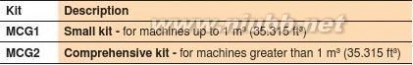
These items are included in the MCG2 kit TP6, TP6A, MIP* and PH50* with suitable adaptors.
* Obsolete products
R = 685 mm (26.97 in) ?
R = 532 mm (20.94 in) ?Additional weightArms
R = 380 mm (14.96 in)
1.5 mm A/F R = 226 mm (8.90 in)
hexagonal keyR = 151 mm (5.95 in)
R = 101 mm (3.98 in)
Calibrated
pivot
76 mm (2.99 in)
127 mm (5.00 in)
235 mm (9.25 in) ?
Mahogany Base plate
storage box
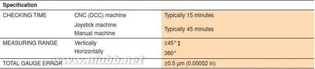
+45°
Calibration traceable to USA National Institute of Standards and Technology
(Ref #731/23897-87). The machine checking gauge also complies with British
Standard BS EN ISO 10360-2.0° R
The probe’s stylus slots into the end of what is in effect a reference ballbar.
The probe carries the bar with it over a circular path, and radial readings are
taken at 0°, +45° and -45° elevations. The range of these readings indicates the
volumetric measuring performance of the CMM. Repetition of a sequence of
readings checks the system for repeatability.-45°
Volumetric measuring performance is the maximum error between any two
points in any plane, over any distance within the full measuring volume.
? Maximum negative arm angle possible is 42°, when using MCG1 kit with the longest arm 320 mm (12.60 in) and both pillars supplied, 127 mm + 76 mm = 203 mm (5 in + 3 in = 8 in)
雷尼绍探针 雷尼绍探针

Probing systems forco-ordinate measuring machines MSR1 manual storage rackThe MSR1 holds up to six pre-quali? ed stylus assemblies for ? tting to TP20 or TP200 probe modules. It eases the operators’ task where manual module changing is performed and thus aids productivity improvements.The MSR1 can be table mounted (as shown) or wall mounted using a bracket. The rack is intended to hold pre-quali? ed stylus assemblies ? tted to TP20 or TP200 probe modules. It provides convenient storage and protects the kinematic coupling mechanism from
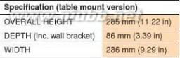
contamination.

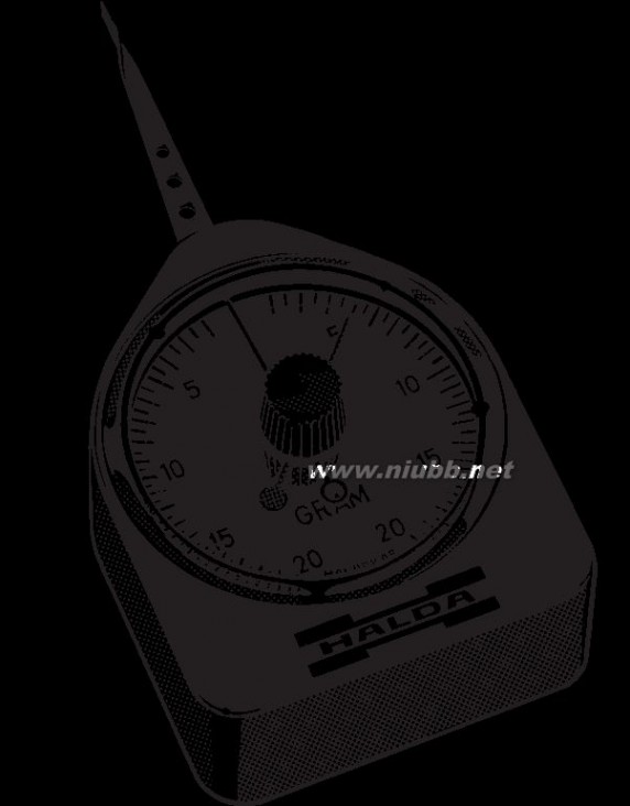
Renishaw’s gram gauge enables the adjustment,
reset and checking of probe trigger force settings
on all standard Renishaw CMM touch-trigger
probes. Setting the optimum trigger force
using the gram gauge maximises a probe’s
performance.
The gram gauge can be used to set trigger force
settings over a range from 4 to 35 grams.
The scale graduations are set at 1 gram intervals
which is suf? cient for all probe trigger force
measurements on CMMs.
Due to the use of SI units, the trigger force for
probes is given in Newtons. The conversion
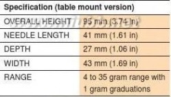
factor used is 1 gf = 0.01 N.
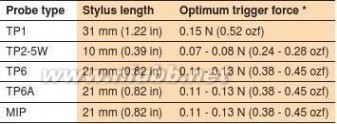
* This is the optimum trigger force recommended by Renishaw.
Higher trigger forces may be required for longer styli.
雷尼绍探针 雷尼绍探针


Styli
Comprehensive information on Renishaw’s styli products can be found in the styli and technical speci? cations document (H-1000-3200).
Accuracy at the point of contact
As industry has developed its requirement for increasingly diverse and complex manufactured parts, inspection systems
have had to work hard to keep up. The use of CMMs with probing systems, and in-process inspection on machine tools, are two of the solutions offered by Renishaw to help you maximise your productivity and maintain the highest possible standards of quality.
Successful gauging depends very much on the ability of the probe’s stylus to access a feature and then maintain accuracy at the point of contact. Renishaw has used its expertise in probe and stylus design to develop a comprehensive range of CMM and machine tool styli to offer the greatest possible precision.
These notes explain the critical features of each stylus type, helping you to choose the right design for each inspection need.
What is a stylus?
A stylus is that part of the measuring system which makes contact with the component, causing the probe mechanism to displace, the generated signal enabling measurement to be taken. The feature to be inspected dictates the type and the size of stylus used. However, in all cases maximum rigidity of the stylus and perfect sphericity of the tip are vital.
The performance of gauging can easily be degraded if a stylus is used with poor ball roundness, poor ball location, bad thread ? t or a compromised design that allows excessive bending during measurement.
To ensure the integrity of the data gathered, make certain that a stylus from the
comprehensive range of genuine Renishaw styli is speci? ed and used.
Choosing a stylus
To maintain accuracy at the point of contact it is recommended that:-? Styli be kept short? Joints be minimised
?

A large as possible styli ball is used
雷尼绍探针 雷尼绍探针

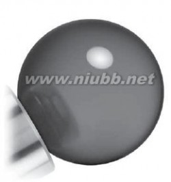
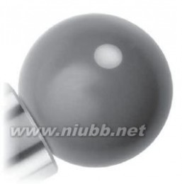
Probing systems forco-ordinate measuring machines Genuine Renishaw styli ball materialsRubyThe industry standard and the optimum stylus ball material for a vast majority of measurement applications is ruby, one of the hardest known materials. Very few applications exist where ruby is not the best ball material. However, there are two such applications where balls manufactured from other materials are recommended, and these are Silicon nitride and Zirconia.Silicon nitrideFor heavy duty scanning applications on aluminium, a phenomenon known as ‘adhesive wear’ can occur, which
involves build up of aluminium from the surface onto the ball. The preferred ball material for this application is Silicon nitride.Silicon nitride possesses many similar properties to ruby. It is a very hard and wear resistant ceramic which can be machined into very high precision spheres. It can also be polished to an extremely smooth surface ? nish. Silicon nitride does not have the attraction to aluminium and so does not exhibit the adhesive wear seen with ruby in similar applications. Silicon nitride does, however, show signi? cant abrasive wear characteristics when scanning steel surfaces so its applications are best con? ned to aluminium.
Zirconia
In heavy duty scanning applications on cast iron. Interaction between the two materials can result in ‘abrasive wear’ of the ruby ball’s surface. For such applications, Zirconia balls are recommended.
Zirconia is a particularly tough ceramic material with hardness and wear characteristics approaching those of ruby. Its surface properties, however, make it an ideal material for aggressive scanning applications on cast iron components.
Stylus types
The genuine Renishaw stylus range comprises several types:Straight styli Cylinder styli
Star styli Pointer styli
Disc styli Ceramic hollow ball styli
Accessories and tools
Stylus centres Stylus thread adaptors
Stylus knuckles Stylus tools
Stylus extensions Stylus cranksRubySilicon nitride
Zirconia
雷尼绍探针 雷尼绍探针


Custom design service
Renishaw’s Styli and Custom Products Division offer a unique service by providing
customers with a total solution should their probing needs for CMM, machine tool or scanning applications be specialised.
In many application problems, the solution lies in the choice of the stylus which in? uences access of the workpiece features, inspection times and probe performance. All of these aspects are considered within the design of a custom stylus, ensuring that the solution provided incorporates the ideal choice of materials and optimises probe performance for a particular application.
Renishaw’s Styli and Custom Products Division has supplied over 5,000 different custom styli into probing applications worldwide, so the solution to an application problem may already exist. For advice and further details, please contact your nearest Renishaw distributor.
For more detailed information please
refer to the styli and accessories technical speci? cations (H-1000-3200).Always use genuine Renishaw styli or your
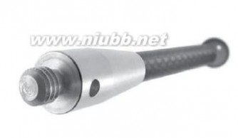
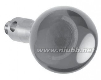
probe performance will be compromised!
雷尼绍探针 雷尼绍探针

Probing systems forco-ordinate measuring machines Glossary of termsAccuracyFor touch-trigger probes, the accuracy is stated in terms of the uncertainty of measurement arising from error sources such as repeatability and pretravel variation.Analogue probeA proportional probe in which the displacement of the stylus is represented by a continuously variable output voltage or current proportional to the displacement.AutojointRenishaw’s patented highly repeatable 2-part coupling, incorporating a 13-pole connector, which allows probes or extension bars to be interchanged without requali? cationContact probeA probe that uses a stylus to physically touch the target gauge point on the workpiece whose co-ordinates are to be recorded.ControllerThe electronic unit that controls the motion and positioning of an actuator or motion
system. Examples are the controllers for a probe head or the axes of a CMM.
DatumThe reference feature (line or plane) from which other co-ordinates are measured.E-bar or ebarAn abbreviated name for extension bar.Edge triggeringThe ability of a non-contact probe to automatically locate the edge or boundary of
contrasting features on the workpiece.
EWLEffective working length.
ExtensionDevice for increasing the reach of a probe or stylus. Extensions placed between the
probe and the probe head are known as ‘extension bars’ or ‘ E-bars’.
Indexing head An articulating probe head that may be oriented and locked in a number of repeatable
kinematically seated spatial positions. After the stylus tips have been quali? ed at each required position, the head may be moved to any of these positions without requali? cation.
JogAn incremental move of an indexing head to an adjacent position.Kinematic seatingA mechanism in which the spatial position of a movable component, when located in the
seated position, is kinematically constrained by 6 contact points formed by a system of rollers (or ‘V’ grooves) and ball bearings.
KinematicA contact probe in which the kinematic seating forms an electrical circuit where the
resistance varies as the stylus is displaced in its mounting, to provide the trigger signal. After displacement, the stylus ball returns to the highly repeatable position de? ned by the kinematic location points.
KinematicsThe science of motion, independent of force.LobingUsed to describe the form measurement error of kinematic switching probes resulting
characteristics from the tri-lobed pretravel pattern (in the X-Y plane) that characterises this type of sensor mechanism. Refer to pretravel variation.
M8 connectorThe threaded 2-pole connector used to mount a range of probes to the probe head.MultiwireThe method of interconnection from a probe head ? tted with a 13-pole autojoint
connector to a probe interface.
OvertravelThe distance that the CMM takes to stop following the assertion of a probe trigger
signal.
Overtravel forceThe force applied by the stylus ball to the surface at a de? ned overtravel displacement.PICSAcronym for Renishaw’s product interconnection system.PretravelThe displacement from the point where the stylus ball contacts the workpiece, to the
point where a probe trigger is asserted.
雷尼绍探针 雷尼绍探针


Pretravel variationAlso called form measurement error or lobing, this source of systematic error is (PTV or XYPTV)predominant in kinematic switching probes where a tri-lobed pretravel pattern (in the X-
Y plane) characterises this type of sensor mechanism.
ProbeThe sensor that locates the features to be gauged, relative to the CMM scales.Probe headA device ? tted to the quill of the CMM that carries the probe mounting connector. Probe
heads may have ? xed orientation or may articulate to provide re-orientation of the probing axis. Articulating heads may be manually operated or motorised.
Probe interfaceAn electronic unit that processes the output from the probe sensor and communicates
with the CMM controller
Proportional probe A displacement measuring probe that provides an output, which may be analogue or
digital, proportional to stylus displacement over a de? ned operating range.
Quali? cationThe procedure in which the measurement processor determines the radius of the stylus
tip and its position relative to the scale reference marks or other datum by gauging a calibrated reference sphere or ring gauge.
QuillThe moving component of the CMM that carries the probe, also called the ram.Repeatability“The quantitative degree of agreement between results of successive measurements of
the same quantity under identical conditions.”
Unidirectional repeatability is speci? ed for touch-trigger probes.
Requali? cationRepetition of the quali? cation procedure that may be necessary after changing or
moving components in the measurement path, or following a change to ambient temperature
Retro? tThe installation of new products or parts onto equipment that is in serviceScanning probeA proportional probe that is passed over the surface of the workpiece in a continuous
movement sending data to the processor at a high rate.
Sense directionsThe directions of gauging relative to the probe’s coordinate system.ServoA motorised articulating probe head that may be oriented to virtually any desired spatial
positioning head position with ? ne resolution. The position is held during probing by the servo control system. High precision rotary position encoders eliminate the need for requali? cation.
ShankA plain or tapered shaft for mounting a probe or probe head to the quill of the CMM.StylusThe part of contact probes that makes physical contact with the feature to be gauged.Stylus changingA system based on a highly repeatable kinematically constrained coupling, to allow the
fast exchange of stylus con? gurations without requali? cation.
Swept radiusOn an articulating probe head, the distance from the centre of rotation of the ‘A’ axis to
the probe or stylus mounting face.
Touch-trigger probeA discrete point taking type of contact probe.Trigger forceThe force that must be applied at the stylus tip to trigger the probe.TTPTouch-trigger probe/probing
Unidirectional repeatability The variation of the position of successive triggers taken in the same direction of
triggering under constant conditions.
雷尼绍探针 雷尼绍探针

Probing systems forco-ordinate measuring machines Product indexAC1 / AC2Interface card for use with SP600/M/Q probes (AC2 has higher resolution)4-13AC3Interface card for use with SP25M probe4-3ACC2-2Controller for ACR1 autochange rack10-2ACR1Autochange rack with 8 ports for changing autojoint mount probes/extensions (requires 10-2ACC2-2 integration)ACR2Autochange rack for PHS17-7ACR3Autochange rack with 4 ports for changing autojoint mount probes/extensions (requires 10-3software integration)AM1Adjustment module for alignment of PH10T/M probe heads8-5AM2Adjustment module for alignment of PH10MQ probe head8-5
FCR25Change rack unit with 3 ports for changing all SP25M probe elements - mounts to MRS4-4FCR25-L3Change rack with 3 ports for changing all SP25M probe elements4-4FCR25-L6Change rack with 6 ports for changing all SP25M probe elements4-4Gram gaugeGram gauge for use when adjusting force on TP2-5W, TP1 (S), TP6, TP6A touch-trigger 13-7
probes
HA-8Interchangeable probe arm, with M8 probe mount, for PHS1 probe head7-4HA-MInterchangeable probe arm, with autojoint probe mount, for PHS1 probe head7-4HCU1Hand held control unit for use with PHC10-2 (re PH10T/M/MQ probe heads)9-2HE330 / 500 / Interchangeable probe arm extension (330/500/750 mm lengths), with M8 probe mount, for 7-4750PHS1 head
IS1-2Interface selector for Renishaw and some third party probes9-3IU80Interpolator unit for use with SP80 probe4-8KM1 / KM2Kinematic quill mount plate for PHS1 probe head7-4KM80Kinematic quill mount plate for SP80 probe4-8MAPSManual autojoint probe stand, for storage of autojoint mount probes/extensions10-4MCGMachine checking gauge for diagnostic testing of CMM axes alignments13-6MCR20Change rack for TP20 stylus modules3-5MCU1Multi-functional hand control unit for use with UCC1 controller9-12MH20Manual articulating probe head with integral mount for TP20 stylus module – shank mount to 6-2
CMM
MH20iManual indexing probe head with integral mount for TP20 stylus module – shank mount to 6-3
CMM
MH8Manual indexing probe head with M8 probe mount - shank mount to CMM5-5MIH / MIH-SManual indexing probe head with an autojoint (non multi-wire) probe mount - shank mount to 5-4
CMM
MRSModular rack system for carrying FCR25, SCP600, SCP80 and ACR3 changer units13-1MS##Shanks - wide selection available (also see page 12-2)12-1MSR1Module storage rack for TP20 and TP200 stylus modules13-7PAA1 / 2 / 3Extension bars - ‘autojoint to M8’ type11-1PEL1 / 2 / 3 / 4Extension bars – ‘M8 to M8’ type11-2PEM1 / 2 / 3 / 25Extension bars - ‘autojoint to autojoint’ type11-1PH1Manual articulating probe head with M8 probe mount - shank mount to CMM5-7
雷尼绍探针 雷尼绍探针


PH10M
PH10MQ
PH10T
PH6
PH6M
PHA1 / PHA2Motorised indexing probe head with multi-wire autojoint probe mount - shank mount to CMMMotorised indexing probe head with multi-wire autojoint probe mount - in-quill mount to CMMMotorised indexing probe head with M8 probe mount - shank mount to CMMFixed probe head with M8 probe mount - shank mount to CMMFixed probe head with multiwire autojoint probe mount – shank mount to CMMProbe head adaptors for rapid interchange between PH10M/T and PHS on the same CMM8-38-38-15-65-67-6PHA3 / PHA80Probe head adaptors for rapid interchange between PH10MQ and SP80 on the same CMM13-4PHC10-2Controller for PH10T/M/MQ probe heads9-2PHS1Motorised (servo type) probe head – mounts to CMM using KM1 or KM27-4PI 200Probe interface for TP200 probe (also for all other standard touch trigger probes excluding 9-1
TP7M)
PI 4-2Interface for standard touch trigger probes (excluding TP7M, TP200, TP800-2)9-1PI 7-2Interface for TP7M probe (also for all other standard touch trigger probes excluding TP200)9-1PK1Knuckle joint: ‘M8 to M8’11-2REVO?Dynamic measuring head and probe system7-1RSP22D tip sensing probe for use with REVO?7-1RSP33D probe for use with REVO?7-1RTP20Compact probe head with DCC capability and integral TP20 touch-trigger probe6-1SCP600Change port unit for changing SH600 stylus holders (re SP600/M/Q probes) - mounts to MRS4-12SCP80Change port unit for changing SH80 stylus holders (re SP80 probe) - mounts to MRS4-8SCR200Change rack for changing TP200 stylus modules (re TP200 probe)3-2SCR600Change rack for changing SH600 stylus holders (re SP600/M/Q probes)4-12SH25-1 / 2 / 3 / 4Stylus holders for use with SM25-1/2/3 scanning modules (re SP25M probe)4-3SH600Stylus holder for SP600/M/Q probe4-12SH80Stylus holder for SP80 probe4-8SM25-1 / 2 / 3 / 4Scanning modules for use with SP25M probe4-3SP25MScanning probe with scanning and TTP functionality and module changing of all system 4-1
elements - autojoint mount to probe head
SP25M / UCC1-Daughtercard for the UCC1 controller to interface with SP25M probe4-3DC
SP600Scanning probe with stylus holder changing - shank mount to CMM4-11SP600MScanning probe with stylus holder changing - autojoint mount to probe head4-11SP600QScanning probe with stylus holder changing - in-quill mount to CMM4-11SP80Scanning probe, ultra-high accuracy performance with stylus holder changing - quill mount to 4-7
CMM using KM80
SP80 / UCC1 DCDaughtercard for the UCC1 controller to interface with SP80 probe4-8SPA2High-power servo power ampli? er9-9SPAliteEntry level 3-axis only servo power ampli? er9-9SPA1Servo power ampli? er for use with UCC1 controller9-11TM25-20Adaptor module to carry TP20 stylus modules on the SP25M probe4-3TP1 (S)Touch-trigger probe, standard kinematic type - shank mount to CMM2-2
雷尼绍探针 雷尼绍探针

Probing systems forco-ordinate measuring machines
TP20 / TP20 NITouch-trigger probe, standard kinematic type with stylus module changing - M8 probe head 3-4
mount
TP20 stylus Stylus module for TP20 probe3-5module
TP200 / TP200BTouch-trigger probe, electronic high-accuracy type with stylus module changing - M8 probe 3-1
head mount
TP200 stylus Stylus module for TP200 probe3-2module
TP2-5WTouch-trigger probe, standard kinematic type - M8 probe head mount2-2TP6Touch-trigger probe, standard kinematic type (higher accuracy than TP2/TP20) - M8 probe 2-3
head mount
TP6ATouch-trigger probe, standard kinematic type (higher accuracy than TP2/TP20) - autojoint 2-3
probe head mount
TP7 / TP7M EPTouch-trigger probe, electronic high-accuracy type - autojoint probe head mount2-1UCC2High-power 4-axis DCC CMM controller9-4UCCliteEntry level 3-axis only controller9-5UCC1Universal CMM controller9-7UDSUniversal datum sphere13-5
雷尼绍探针 雷尼绍探针


雷尼绍探针 雷尼绍探针

Renishaw plc
New Mills, Wotton-under-Edge,
Gloucestershire, GL12 8JR
United KingdomT +44 (0)1453 524524F +44 (0)1453 524901E uk@renishaw.comwww.renishaw.com
For worldwide contact details, please visit our main website at www.renishaw.com/contact

*H-1000-5050-19*
? 2003 - 2006 Renishaw plc Renishaw reserves the right to change speci? cations without noticeIssued 0506 Part no. H-1000-5050-19-A
二 : 雷尼绍探针

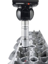

CMM products technical speci? cation
H-1000-5050-19-AProbing systems for

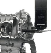
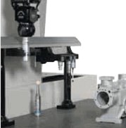
co-ordinate measuring machines
Renishaw’s technology

Renishaw stands at the forefront of automated metrology, with the Group’s products providing manufacturers with the ability to machine components accurately, and perform measurement traceable to international standards. Probe technology, allows fast, highly repeatable measurements to be carried out on co-ordinate measuring machines (CMMs).
A wide range of automated probing systems has been developed to meet the needs of post-process inspection, for quality control.
During the manufacturing operation, probes used on computer numerically controlled (CNC) machine tools provide the measurement capability to automatically control the machining process. This eliminates the need for costly, time consuming manual procedures.
Renishaw gives extra capability to CNC machine tools and CMMs by enabling scanning and digitising of 3-dimensional (3D) forms to generate the necessary NC programs to produce either replica parts, or moulds and dies.
Renishaw has developed the Cyclone scanning machine and associated software, a cost-effective solution to stand-alone digitising.
The revolutionary manufacturing system, RAMTIC (Renishaw’s automated milling, turning and inspection centre), maximises the potential of existing machine tools, enabling milling, turning and inspection on a single machine, together with automated loading and unloading of materials and tools.CNC machine tools and CMMs bene? t from regular volumetric checking by Renishaw’s automated ball-bar and machine checking gauge. Comprehensive machine calibration can be undertaken, when necessary, using Renishaw’s innovative laser calibration systems.Renishaw has developed linear scale, laser interferometer and encoder systems for ? tting to a variety of machines, to provide axis displacement measurement. Dedicated lengths of rigid scale are not required, since Renishaw’s approach has been to produce ? exible scale that can be dispensed from a reel and cut to the required length.Renishaw has also applied its innovatory approach to produce a Raman microscope and accessories for 2D spectral analysis of materials in a non-destructive manner.From its leading market position, the Renishaw Group continues to expand its product range into ever increasing business sectors worldwide. Identifying and targeting new market opportunities has led to the continuous development and introduction of new, highly innovative products which signi? cantly enhance the manufacturing capabilities


in a wide range of industries.

Probing systems for
co-ordinate measuring machines
Introduction to CMM probing
CMMs are used for a wide variety of industry applications, especially for post-process inspection of manufactured components. Renishaw’s probes and probing systems have become the industry choice for rapid and accurate inspection. CMMs, which act as a quality reference, use probing
systems to replace traditional manually operated measuring instruments such as micrometers, vernier callipers and dedicated gauges.
Contents1
How to use this guide
2 Touch-trigger probes
without stylus module changing
3 Touch-trigger probes
with stylus module changing
Probe systems
Renishaw’s probe systems are available in a wide variety of
types to enable a best match for a particular application.
4 Scanning probes5 6 7 8 9
Manual probe heads
with integral M8/autojoint probe mount
Fitting the probe on the CMM
The probe is mounted on the CMM via a probe head. The
type of head is determined by the ? exibility and automation required. Renishaw has designed a range of probe heads for manual and automated systems.
Motorised heads maximise probing ef? ciency and give a 3-axis CMM, 5-axis capability. A motorised head can also be used with Renishaw’s autochange systems which allows rapid and automatic exchange of multiple probe types and extension combinations.
Manual probe heads
with integral TP20 stylus module mount
Motorised probe heads
servo type
Motorised probe heads
indexing type
Advanced control
Traditionally, scanning has been limited to relatively slow machines but Renishaw’s universal CMM controller family enables this function at speeds many times faster than was previously possible.
Interfaces and controllers
10 Change/storage racks
for autojointed probes/extensions
11 Extension bars
Accessories
The range of accessories enhances the basic system by
offering additional capability such as stylus changing for the probe, probe sensor changing for multiple probe requirements and extension bars to provide access to deep features. Renishaw supplies a comprehensive range of styli for
component inspection and scanning applications which are available in a variety of pro? les, sizes and ? ttings to best suit the probe employed and the components’ features and dimensions.
To avoid the risk of compromising measurement performance, always use a replacement stylus from Renishaw!
12 Shanks13 Accessories
14 Styli and custom design service15 Glossary of terms16 Product index

Probing systems for
co-ordinate measuring machines
How to use this guide
This TECHNICAL SPECIFICATIONS document is intended to help you select the most appropriate probing system for your CMM. The probing system includes the probe with stylus, the method of attachment of the probe to the CMM
by use of a probe head or simple shank, and the necessary
probe/head controlling interfaces.
Probe system selection
Before selecting the most appropriate probe system, you should clearly understand the scope of measurement applications to be addressed on your CMM. Renishaw’s product range covers all types of probing requirements, from simple touch-trigger point measurement through to advanced part pro? le scanning. Where a standard product proves not to be ideal, Renishaw’s custom design service is available to accommodate you requirements.
This technical speci? cations document is divided into sections that focus on the different parts of the probing system and indicates the particular bene? ts of each product. The technical information for each product is also given so that performance data can be compared where more than one product appears suitable.
Step-by-step selection procedure
Step 1 (see sections 5, 6, 7 and 8)Systems suitable for your CMM
Q? Which type of CMM do you have or wish to purchase?Manual CMM - go to sections 5/6 to see the family trees of probing systems that are suited to manual CMMs. Identify the probe(s) and probe head(s) that are of interest, and then proceed to steps 2 and 3 to ? nd out more information on these products and ? nalise your selection.
DCC CMM - go to sections 7/8 to see the family trees of probing systems that are suited to DCC CMMs. Identify the probe(s) and probe head(s) that are of interest, and then proceed to steps 2 and 3 to ? nd out more information on these products and ? nalise your selection.
NOTE: All probes shown in this document are suitable for use on DCC CMMs.
Step 2 (see sections 2/3/4)Probe selection
Detailed information on each probe is given in one of three sections as described below.
Contact trigger probes (see sections 2 and 3)
Discrete point, contact trigger probes (also called touch-trigger probes) are ideal for inspection of 3
dimensional prismatic parts and known geometries. These probes are highly versatile and are suitable for a diverse range of applications, materials and surfaces, and there is a wide range of accessories available for them. The probes are segregated into two sections here - probes without, and probes with stylus module changing. Stylus module changing is a very important consideration as it enables higher productivity and the ability to always select the best measurement solution for the application. A further distinction between contact trigger probes is their type of design. There are kinematic probes and electronic probes to choose from. Probe sizes vary due to the features of the probe. The larger kinematic probes are extremely robust and are very well suited to manual CMMs due to their large overtravel capability. The smaller probes are suited to applications where there is a need to access restricted spaces. Renishaw’s electronic probes offer extended life suitable for high density point pro? le measurement and also permit higher accuracy than kinematic probes. Depending on the type of CMM and the level of utility required, there is a choice between shank mounted, M8 thread or autojoint mounted probes. Renishaw’s autojoint mounted probes and extensions can be rapidly interchanged for increased ? exibility and productivity.
Contact scanning probes (see section 4)
Scanning is ideal for the inspection of geometric forms and full pro? le measurement where thousands of data points can describe the form more fully than a few discrete points. A large amount of information can be collected in a very short time giving better direct results. Renishaw’s range of ? xed and indexable type scanning probes offers high accuracy, excellent robustness and low contact force scanning. All Renishaw scanning probes feature rapid interchange between stylus con? gurations to further increase ? exibility and productivity.


Step 3 (see sections 5/6/7/8)Probe head selection
Having selected the probe type, refer again to the family trees (sections 5 and 6 for manual CMMs or sections 7 and 8 for DCC CMMs) to see which probe head(s) are suitable.Manual CMMs - are usually ? tted with shank-mounted probes or manual probe heads. Renishaw offer varieties of manual probe heads which are segregated into sections 5/6 here detailing manual probe heads with integral M8/autojoint or with integral TP20 stylus module mount. A further design consideration is the choice of ? xed or articulating/indexing manual head types. The type of probe head required can be determined by examining the features of each head and matching them to your requirements.
DCC CMMs - can be ? tted with either manual or motorised probe head systems, so the choice must be made having considered the applications of the CMM. Motorised heads are segregated into sections 7/8 here detailing servo type and indexing type motorised heads. Fitting the probe on a CMM using a motorised head is the easiest way to vastly improve the capability of the CMM and maximise productivity. The indexing type motorised heads are designed to position the probe at one of 720 positions, in 7.5° steps, so probing can be carried out at many angles. The repeatability of the head means that these positions can be recalled at any time without the need for re-quali? cation. This can save a great deal of time for the operator, and encourages system optimisation by applying the probe to the surface at the best angle for the most
accurate result. Servo type motorised heads provide almost unlimited angular positioning and are ideally suited to horizontal arm CMMs.
Step 4 (see section 9)
Probe / probe head, interface selection
The probe data in sections 2, 3 and 4 de? nes the electrical interface(s) compatible with the chosen probe. See section 9 for full details of probe interfaces.
The probe head data in sections 5, 6, 7 and 8 de? nes the type of controller required to integrate the probe head into the CMM. See section 9 for full details of probe head interfaces.
Step 5 (see sections 11 and 12)Extension bar / shank selection
For probes and probe heads that are shank mounted on the CMM, go to section 12 to choose the appropriate shank. Section 11 details a comprehensive range of extension bars to enhance the versatility of your probe system. Remember that Renishaw offers a custom design service if the type of shank/extension you require is not a standard product.
Step 6 (see sections 2, 3, 4 and 10)Changer system selection
Many of Renishaw’s probes, when ? tted to DCC CMMs, are capable of rapid automatic interchange between stylus con? gurations or even between different types of probe. Refer to sections 2, 3 and 4 to see if your chosen probe has change rack compatibility, and for details of these highly productive systems. Renishaw’s autochange rack systems allow rapid exchange between probe sensors and extensions with the Renishaw autojoint and are detailed in section 10.
Step 7 (see section 13)Accessories
Check the accessories section 13, for other accessories available for your chosen probe system.
Step 8 (see section 14)Stylus selection
Renishaw produces a wide range of styli designed to optimise measurement performance. A brief overview is given in section 14. Please also see Renishaw’s Styli and accessories guide (part number H-1000-3200) for comprehensive details.
NOTE: Section 15 contains a glossary of terms used in this document.
This document contains information on Renishaw’s current CMM products range. If you require additional information on these and discontinued products, please visit our website: www.61k.com

Probing systems for
co-ordinate measuring machines

TP7M / TP7M EP probes
The TP7M range comprises electronic probes using strain gauge technology which gives higher accuracy )
)
than kinematic touch-trigger probes. Incorporating a m nnii 75multiwired autojoint connection, the TP7M is compatible n)
90..12(with the PH10M/PH10MQ motorised heads, PH6M ? xed ( mmprobe head, and the range of PEM extension bars.mm
)
mn02im 55The autojoint also allows fast probe changing, either 9 07.manually or automatically, with a Renishaw autochange m 20(rack system.
n)The enhanced performance TP7M EP is capable M4 × 0.7 thread
of achieving a 3D accuracy of <0.6 μm tested to ISO 10360 Pt 2.
16°
16°
5 mm (0.20 in)+Z overtravelMaximum 5 mm (0.20 in)XY overtravel
-Z overtravel
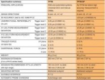
PI 7-2 probe interface
The PI 7-2 interface has two switchable levels of trigger sensitivity to accommodate differing applications. Please see section 9 for full details.
Above data applies for test conditions as follows: Stylus length 50 mm (1.97 in) Stylus velocity 240 mm/min (1.57 ft/min)* Test performed on a CMM speci? cation U3 = 0.48 μm + L/1000
本文标题:雷尼绍探针-雷尼绍探针61阅读| 精彩专题| 最新文章| 热门文章| 苏ICP备13036349号-1