一 : 推荐:最新RSS 2.0规范(中文版)大全
英文原版请参见http://blogs.law.harvard.edu/tech/rss
RSS是 Really Simple Syndication的缩写(对rss2.0而言,是这三个词的缩写,对rss1.0而言则是RDF Site Summary的缩写,1.0与2.0走的是两个体系)。
RSS 基于XML,所有的 RSS 必须遵循w3c网站上公布的XML 1.0 规范。
在一个RSS文档中,根元素是<rss>,带有一个必备属性version,用以指明该文档遵循的rss规范,如果rss文档遵循本规范,则version值必须是2.0。
<rss>元素只有一个子元素,包含关于频道的一些信息。频道(channel)是整个blog,项(item)指一篇文章或日志(也有称这为post)。
RSS2.0元素channel的子元素列表
| 元素(Element) | 描述(Description) | 值域 | 重要性 | 举例(Example) |
| title | 频道名称 | 必备 | GoUpstate.com News Headlines | |
| link | 频道的URL | 必备 | http://www.goupstate.com/ | |
| Description | 频道的描述 | 必备 | The latest news from GoUpstate.com, a Spartanburg Herald-Journal Web site. | |
| language | 频道文章所用语言, | 可用netscape或w3c推荐的列表 | 可选 | en-us |
| copyright | 频道内容的版权说明 | 可选 | Copyright 2002, Spartanburg Herald-Journal | |
| managingEditor | 责任编辑的email | 可选 | geo@herald.com (George Matesky) | |
| webMaster | 负责频道技术事务的网站管理员email | 可选 | betty@herald.com (Betty Guernsey) | |
| pubDate | 频道内容发布日期,格式遵循RFC822格式(年份可为2们或4位) | 可选 | Sat, 07 Sep 2002 00:00:01 GMT | |
| lastBuildDate | 频道内容最后的修改日期 | 可选 | Sat, 07 Sep 2002 09:42:31 GMT | |
| category | 指定频道所属的一个或几个类别 | 可选 | <category>Newspapers</category> | |
| generator | 生成该频道的程序名 | 可选 | MightyInHouse Content System v2.3 | |
| docs | 指向该RSS文件所用格式说明的URL | 可选 | http://blogs.law.harvard.edu/tech/rss | |
| cloud | Allows processes to register with a cloud to be notified of updates to the channel, implementing a lightweight publish-subscribe protocol for RSS feeds. More info here. | 可选 | <cloud domain="rpc.sys.com" port="80" path="/RPC2" registerProcedure="pingMe" protocol="soap"/> | |
| ttl | 有效期,用以指明该频道可被缓存的最长时间 | 分钟为单位 | 可选 | <ttl>60</ttl> |
| image | 指定一个 GIF或JPEG或PNG图片,用以与频道一起显示 | 可选 | ||
| rating | 这个频道的分级(主要指成人、限制、儿童等) | 可选 | ||
| textInput | 指定一个text输入框供用户输入,具体信息及功能未定。 | 可选 | ||
| skipHours | 提示新闻聚合器,那些小时时段它可以跳过。 | 可选 | ||
| skipDays | 提示新闻聚合器,那些天它可以跳过。 | 可选 |
RSS2.0元素channel的子元素image的子元素列表
| 元素(Element) | 描述(Description) | 值域 | 重要性 | 举例(Example) |
| url | 图片的url | 必备 | ||
| title | 图片的标题,用于http的alt属性 | 必备 | ||
| link | 网站的url(实际中常以频道的url代替) | 必备 | ||
| width | 图片的宽度(象素为单位) | 最大144,默认88 | 可选 | |
| height | 图片的高度(象素为单位) | 最大400,默认31 | 可选 | |
| description | 用于link的title属性 | 可选 |
RSS2.0元素channel的子元素cloud的子元素列表
| 元素(Element) | 描述(Description) | 值域 | 重要性 | 举例(Example) |
| domain | Cloud程序所在机器的域名或IP地址 | radio.xmlstoragesystem.com | ||
| port | 访问clound程序所通过的端口 | 80 | ||
| path | 程序所在路径(不一定是真实路径) | /RPC2 | ||
| registerProcedure | 注册的可提供的服务或过程 | xmlStorageSystem.rssPleaseNotify | ||
| protocol | 协议 | xml-rpc, soap , http-post 之一 |
RSS2.0元素channel的子元素textInput的子元素列表
| 元素(Element) | 描述(Description) | 值域 | 重要性 | 举例(Example) |
| title | Submit按钮的标签 | 必备 | ||
| description | 解释text输入区 | 必备 | ||
| name | Text area对象的名字 | 必备 | ||
| link | 处理提交的请求的cgi程序 | 必备 |
二 : RF_TS_EDR蓝牙测试规范2.0
Core System Package
Part A
Radio FrequencyTest Suite Structure (TSS) andTest Purposes (TP)
System Specification 1.2/2.0/2.0 + EDRThis document defines the TSS and TP for qualification testing of the
Bluetooth? Wireless Technology Radio layer.
Issued
21 March 2005
Revision
2.0.E.3
Document No
RF.TS/2.0.E.3
rf2.0 RF_TS_EDR蓝牙测试规范2.0
BLUETOOTH TEST SPECIFICATION Ver. 1.2/2.0/2.0 + EDR [vol 2]Radio Frequencypage 2 of 72CONTENTS
1
2
3Scope....................................................................................................5Normative References.........................................................................7Definitions and Abbreviations............................................................9
3.1Definitions....................................................................................9
3.2Abbreviations...............................................................................9
Test Suite Structure...........................................................................11
4.1Overview....................................................................................11
4.2Test suite structure (TSS)..........................................................11
4.3Test groups................................................................................12
4.3.1Protocol groups.............................................................12
4.3.2Main test group.............................................................12
4.3.2.1Capability (CA) tests.......................................12
4.3.2.2Valid Behavior (BV) tests................................12
4.3.2.3Invalid Behavior (BI) tests...............................13
4.4Provisional RF Testing...............................................................13
Test Purposes (TP).............................................................................15
5.1Introduction................................................................................15
5.1.1TP definition conventions..............................................15
5.1.2TP naming conventions.................................................15
5.1.3TRM/CA/01/C (Output Power)......................................15
5.1.4TRM/CA/02/C (Power Density).....................................18
5.1.5TRM/CA/03/C (Power Control)......................................20
5.1.6TRM/CA/04/C (TX Output Spectrum –
Frequency range)..........................................................22
5.1.7TRM/CA/05/C (TX Output Spectrum –
20 dB Bandwidth)..........................................................25
5.1.8TRM/CA/06/C (TX Output Spectrum –
Adjacent channel power)...............................................27
5.1.9TRM/CA/07/C (Modulation Characteristics)..................29
5.1.10TRM/CA/08/C (Initial Carrier Frequency Tolerance).....31
5.1.11TRM/CA/09/C (Carrier Frequency Drift)........................33
5.1.12TRM/CA/10/C (EDR Relative Transmit Power).............35
5.1.13TRM/CA/11/C (EDR Carrier Frequency Stability and
Modulation Accuracy)....................................................37
5.1.14TRM/CA/12/C (EDR Differential Phase Encoding).......40
5.1.15TRM/CA/13/C (EDR In-band Spurious Emissions).......41
5.1.16RCV/CA/01/C (Sensitivity – single slot packets)...........44
21 March 2005452
rf2.0 RF_TS_EDR蓝牙测试规范2.0
BLUETOOTH TEST SPECIFICATION Ver. 1.2/2.0/2.0 + EDR [vol 2]Radio Frequencypage 3 of 725.1.17
5.1.18
5.1.19
5.1.20
5.1.21
5.1.22
5.1.23
5.1.24
6RCV/CA/02/C (Sensitivity - multi-slot packets)..............46RCV/CA/03/C (C/I performance)...................................48RCV/CA/04/C (Blocking performance)..........................50RCV/CA/05/C (Intermodulation Performance)..............52RCV/CA/06/C (Maximum Input Level)...........................53RCV/CA/07/C (EDR Sensitivity)....................................54RCV/CA/08/C (EDR BER Floor Performance)..............56TP/RCV/CA/09/C (EDR C/I Performance)....................575.1.25RCV/CA/10/C (EDR Maximum Input Level)..................59Annex..................................................................................................61
6.1Reference Signal Definition........................................................61
6.1.12 Mbps Reference Signal (EDR)...................................62
6.1.23 Mbps Reference Signal (EDR)...................................63
6.2Provisional RF Testing (EDR)....................................................63
6.3Frequencies for testing...............................................................63
6.3.1Operating frequency bands...........................................63
扩展:蓝牙rf性能测试规范 / 蓝牙2.1 edr / 蓝牙edr
6.3.2Frequencies for testing, loopback, hopping off..............63
6.3.3Frequencies for testing, TX-Test, hopping off................64
6.4Normal test conditions................................................................65
6.4.1Normal temperature and humidity.................................65
6.4.2Nominal Power source..................................................65
6.4.2.1Mains Voltage.................................................65
6.4.2.2Lead-acid battery power sources
used on vehicles.............................................66
6.4.2.3Other power sources......................................66
6.5Extreme test conditions..............................................................66
6.5.1Extreme temperatures...................................................66
6.5.2Extreme power source voltages....................................66
6.5.2.1Main voltage....................................................66
6.5.2.2Lead-acid battery power source
used on vehicles.............................................66
6.5.2.3Power sources using other
types of batteries............................................67
6.5.2.4Other power sources......................................67
6.6Bit error rate (BER) measurements............................................67
6.7Definition of the position of Bit p0...............................................69
6.8Definition of the reference sensitivity level.................................69
6.9Antenna gain..............................................................................69
6.10Measurement Uncertainty..........................................................69
6.10.1Conducted measurements:...........................................69
6.10.2Relative RF power.........................................................70
21 March 20053
rf2.0 RF_TS_EDR蓝牙测试规范2.0
BLUETOOTH TEST SPECIFICATION Ver. 1.2/2.0/2.0 + EDR [vol 2]Radio Frequencypage 4 of 726.10.3Radiated measurements...............................................70
6.10.4Absolute radio frequency..............................................70
6.10.5Relative drift radio frequency........................................70
6.10.6Peak frequency deviation..............................................70
6.11Test Case Mapping....................................................................70421 March 2005
rf2.0 RF_TS_EDR蓝牙测试规范2.0
BLUETOOTH TEST SPECIFICATION Ver. 1.2/2.0/2.0 + EDR [vol 2]Radio Frequencypage 5 of 721 SCOPE
This Bluetooth document contains the Test Suite Structure (TSS) and Test Pur-poses (TP) to test the Bluetooth RF layer including Enhanced Data Rate.The objective of this Test Specification is to provide a basis for conformance tests for Bluetooth devices giving a high probability of air interface inter-opera-bility between different manufacturer's Bluetooth devices.
The following revisions are applicable to this document.Revision
D5r3
D10R00
D10r01
1.2.1
1.2.2
1.2.3
2.0.E.0
2.0.E.1
2.0.E.2
Draft
2.0.E.2
2.0.E.3r1Date2003-11-052004-03-032004-03-152004-03-252004-07-012004-08-242004-10-192004-10-282004-10-292004-11-042005-02-17DescriptionOriginal ReleaseRe-partitioned to match Main Specification Volume/Part parti-tioning.Editorial changesEditorial changes. Changed document numbering and revision number to conform with legacy system.Changed page numbering to begin part with page 1 and made editorial changes to accommodate Vol. 1, Part A.Incorporated TSE 522 changing TP TRM/CA/06/CIncorporated changes for V2.0 + EDR Editorial correction to TP RCV/CA/10/CEditorial correction to TP RCV/CA/07/CFirst version for 1.2/2.0/2.0 + EDR available for qualificationIncorporate TSE 686 for the TCMT test cases TRM/CA/10/C,
TRM/CA/11/C, TRM/CA/12/C, TRM/CA/13/C, RCV/CA/07/C,
RCV/CA/08/C, RCV/CA/09/C, RCV/CA/10/C.
Incorporate TSE 687 for RCV/CA/08/C.
Incorporate TSE 688 for TRM/CA/13/C.
Incorporate TSE 689 for TRM/CA/11/C.
Incorporate TSE 690 for RCV/CA/07/C.
2.0.E.32005-03-21Prepare for publication.
Scope21 March 20055
rf2.0 RF_TS_EDR蓝牙测试规范2.0
BLUETOOTH TEST SPECIFICATION Ver. 1.2/2.0/2.0 + EDR [vol 2]Radio Frequencypage 6 of 72621 March 2005Scope
rf2.0 RF_TS_EDR蓝牙测试规范2.0
BLUETOOTH TEST SPECIFICATION Ver. 1.2/2.0/2.0 + EDR [vol 2]Radio Frequencypage 7 of 722 NORMATIVE REFERENCES
This Bluetooth document incorporates, by dated or undated reference, provi-sions from other publications. These normative references are cited at the appropriate places in the text and the publications are listed hereafter. For
dated references, subsequent amendments to or revisions of any of these pub-lications apply to this Bluetooth document only when incorporated in it by amendment or revision. The normative references listed below represent the most current versions as of the date of publication of this document. The most current version of a listed reference should be used unless a specific version is noted in the list.[1]
扩展:蓝牙rf性能测试规范 / 蓝牙2.1 edr / 蓝牙edr
[2]
[3]Specification of the Bluetooth System, Core System Package, Volume 2, Part ASpecification of the Bluetooth System, Core System Package, Volume 3, Part DETS 300 328: "Radio Equipment and Systems (RES); Wideband transmission sys-
tems; Technical characteristics and test conditions for data transmission equipment operating in the 2,4 GHz ISM band and using spread spectrum modulation tech-
niques"
FCC Part 15: CFR 47, Part 15 "Radio Frequency Device", Sections 15.205, 15.209, 15.247
PICS Proforma for Radio (RF)[4][5]
Normative References21 March 20057
rf2.0 RF_TS_EDR蓝牙测试规范2.0
BLUETOOTH TEST SPECIFICATION Ver. 1.2/2.0/2.0 + EDR [vol 2]Radio Frequencypage 8 of 72821 March 2005Normative References
rf2.0 RF_TS_EDR蓝牙测试规范2.0
BLUETOOTH TEST SPECIFICATION Ver. 1.2/2.0/2.0 + EDR [vol 2]Radio Frequencypage 9 of 723 DEFINITIONS AND ABBREVIATIONS
3.1 DEFINITIONS
For the purpose of this Bluetooth document, the definitions given in Specifica-tion of the Bluetooth System, Volume 2, Part A apply. In addition, the following definitions apply:
Additional definitions in this Test Specification are given in Volume 1, Part A, Test Strategy and Terminology Overview.
Mathematical conventions used in this document comply with the definitions given in Volume 1, Part A, Test Strategy and Terminology Overview.
3.2 ABBREVIATIONS
For the purpose of this Bluetooth document, the abbreviations given in Volume 1, Part A, Test Strategy & Terminology Overview are applicable.
Definitions and Abbreviations21 March 20059
rf2.0 RF_TS_EDR蓝牙测试规范2.0
BLUETOOTH TEST SPECIFICATION Ver. 1.2/2.0/2.0 + EDR [vol 2]Radio Frequencypage 10 of 721021 March 2005Definitions and Abbreviations
rf2.0 RF_TS_EDR蓝牙测试规范2.0
BLUETOOTH TEST SPECIFICATION Ver. 1.2/2.0/2.0 + EDR [vol 2]Radio Frequencypage 11 of 724 TEST SUITE STRUCTURE
4.1 OVERVIEW
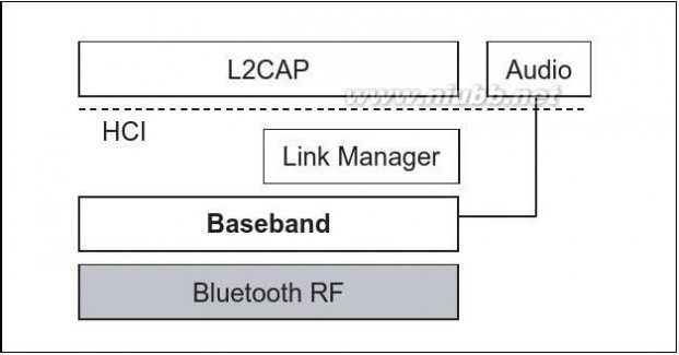
The Bluetooth RF is layer 1 of the Bluetooth protocol stack.
Figure 4.1: Bluetooth protocol stack, Basic Layers4.2 TEST SUITE STRUCTURE (TSS)
Bluetooth RF Test Suite Structure
Transmitter
Output Power
Power Density
Power Control
TX Output Spectrum-Frequency Range
TX Output Spectrum-20 dB Bandwidth
TX Output Spectrum-Adjacent Channel Power
Modulation Characteristics
InitialCarrier Frequency Tolerance
Carrier Frequency Drift
Receiver
Sensitivity – Single slot packets
Sensitivity – Multi slot packets
C/I Performance
Blocking Performance
Intermodulation Performance
Maximum Input Level
Figure 4.2: Test suite structure for Bluetooth RF
Test Suite Structure21 March 200511
rf2.0 RF_TS_EDR蓝牙测试规范2.0
BLUETOOTH TEST SPECIFICATION Ver. 1.2/2.0/2.0 + EDR [vol 2]Radio Frequencypage 12 of 72Bluetooth EDR RF Test Suite Structure
Transmitter
Enhanced Data Rate Relative Transmit Power
Enhanced Data Rate Carrier Frequency Stability and Modulation Accuracy
Enhanced Data Rate Differential Phase Encoding
Enhanced Data Rate In-Band Spurious Emission
Enhanced Data Rate Sensitivity
Enhanced Data Rate BER Floor Sensitivity
Enhanced Data Rate C/I Performance
Enhanced Data Rate Maximum Input Level Receiver
Figure 4.3: Test suite structure for Bluetooth EDR RF
4.3 TEST GROUPS
The test groups are organized in 3 levels. The first level defines the protocol groups representing the protocol services. The second level, separates the protocol services in functional modules. The last level in each branch contains the standard ISO subgroups BV and BI (not shown in Figure 4.3 on page 12).
4.3.1 Protocol groups
The protocol group identifies the kind of test for Bluetooth RF test purposes: ?Transmitter
?Transceiver
?Receiver
4.3.2 Main test group
The main test groups are the capability group, the valid behavior group and the invalid behavior group.This sub group provides testing of the major EUT capabilities aiming to insure that the claimed capabilities are correctly supported, according to the ICS.This sub group provides testing to verify that the EUT reacts in conformity with the Bluetooth standard, after receipt or exchange of a valid Protocol Data Units (PDUs). Valid PDUs means that the exchange of messages and the content of the exchanged messages are considered as valid.1221 March 2005Test Suite Structure
rf2.0 RF_TS_EDR蓝牙测试规范2.0
BLUETOOTH TEST SPECIFICATION Ver. 1.2/2.0/2.0 + EDR [vol 2]Radio Frequencypage 13 of 72This sub group provides testing to verify that the EUT reacts in conformity with the Bluetooth standard, after receipt of a syntactically or semantically invalid PDU.
扩展:蓝牙rf性能测试规范 / 蓝牙2.1 edr / 蓝牙edr
4.4 PROVISIONAL RF TESTING
Certain deviations from the test procedures shall be permitted for an interim period, as specified in Provisional RF Testing (EDR) 6.2 on page 63.
Test Suite Structure21 March 200513
rf2.0 RF_TS_EDR蓝牙测试规范2.0
BLUETOOTH TEST SPECIFICATION Ver. 1.2/2.0/2.0 + EDR [vol 2]Radio Frequencypage 14 of 721421 March 2005Test Suite Structure
rf2.0 RF_TS_EDR蓝牙测试规范2.0
BLUETOOTH TEST SPECIFICATION Ver. 1.2/2.0/2.0 + EDR [vol 2]Radio Frequencypage 15 of 725 TEST PURPOSES (TP)
5.1 INTRODUCTION
5.1.1 TP definition conventions
The TPs are defined following the particular rules of TP Definition Conventions in Test Strategy & Terminology Overview, Volume 1 Part A.
5.1.2 TP naming conventions
The identifier of the TP: TP/<feat>/<xx>-<nn>-<y> is built according to the
standard defined by "TP Naming Conventions" in Test Strategy & Terminology Overview, Volume 1 Part A.
Features/ functions tested for this specification are:
Identifier
Transmitter Tests
Transceiver Tests
Receiver Tests
Table 5.1: TP Naming ConventionsFeature Identifier <feat>TRMTRCRCV
5.1.3 TRM/CA/01/C (Output Power)
Verification of the maximum peak and average RF-output power.
?Reference
ETS 300 328 (subclause 5.2.1),
Bluetooth Specification V1.2 [Vol. 2, Part A] Section 3 on page 33.Test Purposes (TP)21 March 200515
rf2.0 RF_TS_EDR蓝牙测试规范2.0
BLUETOOTH TEST SPECIFICATION Ver. 1.2/2.0/2.0 + EDR [vol 2]Radio Frequencypage 16 of 72?Initial Condition
a)EUT is connected to the tester via 50 ohm connector or a
temporary 50 ohm connector or if there is no antenna connector, via a suitable coupling device.
b)EUT in test mode loop back or TX mode.
c)Hopping on.
d)If EUT supports power control the tester sets the EUT's output power setting to maximum using LMP commands.
?Test Procedure
a)Tester transmits longest supported DM or DH packet with full
payload (1, 3 or 5 slot) with PRBS 9 as payload to the EUT. (See “Reference Signal Definition” on page61.)
1621 March 2005Test Purposes (TP)
rf2.0 RF_TS_EDR蓝牙测试规范2.0
BLUETOOTH TEST SPECIFICATION Ver. 1.2/2.0/2.0 + EDR [vol 2]Radio Frequencypage 17 of 72b)The spectrum analyzer settings shall be as follow:
- Center frequency: the lowest operating frequency
- Span: Zero Span
- Resolution Bandwidth: 3 MHz
- Video Bandwidth: 3 MHz
- Detector: Peak
- Mode: Maxhold
- Sweeptime: depending on packet type (one complete packet)
- Trigger: extern (to signalling unit.)
c)The first time the EUT transmits a burst on the spectrum analyzer
center frequency it is triggered to make a sweep over the duration
of the burst.
d)The tester records the highest power value PPK in the trace.
e)Tester calculates average power PAV over at least 20% to 80% of
the duration of the burst (position of p0 defines the begin of the
burst)
or
if the measuring system is not able to determine the p0 bit in the
burst:
Tester calculates average power PAV over at least 20% to 80% of
the duration of the burst. (The duration of the burst is the time
between the leading and trailing 3 dB points compared to the
average power).
f)Repeat b) to e) while the analyzer centre frequency is set to:
the mid operating frequency; and the highest operating frequency.
These frequencies are defined in Frequencies for testing, loopback,
hopping off 6.3.2 on page 63.
NOTE: When using test equipment that can follow the hopping sequence the low, mid, and upper frequencies can be tested when hopped to.
g)Repeat step a) to f) for all country specific hopping modes.
h)Step a) to g) is repeated under extreme test conditions.
i)The antenna gain G (in dBi,) is added to the results (in dBm)
measured in part a) to i) (only for verdicts 1) and 2) in Expected
Outcome ? on page 18.)
?Test Condition
This test case must be performed at normal and extreme test conditions.Test Purposes (TP)21 March 200517
rf2.0 RF_TS_EDR蓝牙测试规范2.0
BLUETOOTH TEST SPECIFICATION Ver. 1.2/2.0/2.0 + EDR [vol 2]Radio Frequencypage 18 of 72?Expected Outcome
All values as measured must fulfil the following conditions.
1.
2.
3.
4.
5.PAV < 100 mW (20 dBm) EIRPPPK < 200 mW (23 dBm) EIRP If the EUT is a power class 1 equipment:PAV > 1 mW (0 dBm) If the EUT is a power class 2 equipment:0.25 mW (-6 dBm) < PAV < 2.5 mW ( 4 dBm) If the EUT is a power class 3 equipment:
PAV < 1 mW (0 dBm.)
?Uncertainties
?Notes
In the ETS 300 328 the measurement method based on a combination with diode detector and oscilloscope is described. This measurement method is not up to date. An equivalent method for a Bluetooth device based on a spectrum analyzer can be used as described in the previous chapter.
扩展:蓝牙rf性能测试规范 / 蓝牙2.1 edr / 蓝牙edr
The test case should be performed using loopback mode. If so, the test sys-tem must ensure that the testcase is not failed due to not correctly recog-nized return packets or payload failure, i.e: The test system must provide a means to check the correct packet type. In addition it is recommended that the payload content is checked as well if required.
However, if it is required and the test system does not provide a means to distinguish packet types, the TX mode might be used instead if supported by both, test system and IUT.
5.1.4 TRM/CA/02/C (Power Density)
Verification of the maximum RF-output power density.
?Reference
ETS 300 328 (subclause 5.2.2).
1821 March 2005Test Purposes (TP)
rf2.0 RF_TS_EDR蓝牙测试规范2.0
BLUETOOTH TEST SPECIFICATION Ver. 1.2/2.0/2.0 + EDR [vol 2]Radio Frequencypage 19 of 72?Initial Condition
a)EUT is connected to the tester via 50 ohm connector or a
temporary 50 ohm connector or if there is no antenna connector, via a suitable coupling device.
b)EUT in test mode loop back or TX mode.
c)Hopping on.
d)If EUT supports power control the tester sets the EUT's output power setting to maximum using LMP commands.
?Test Procedure
a)Tester transmits longest supported DM or DH packet with full
payload (1, 3 or 5 slot) with PRBS 9 as payload to the EUT. (See “Reference Signal Definition” on page61.)
b)The spectrum analyzer settings shall be as follow:
- Center frequency: 2441 MHz
- Span: 240 MHz
- Resolution Bandwidth: 100 kHz
- Video Bandwidth: 100 kHz
- Detector: Peak
- Mode: Maxhold
- Sweeptime: 1 sec per 100 kHz span
- Trigger: freerun.
If the measurement equipment is not able to store one sample
for each 100 kHz frequency range, the span may be split for
several measurements.
c)A trace is done and the peak value of the trace is found.
d)The spectrum analyzer is set to Zero Span, the center frequency is set to the frequency found in step c), and the sweep time is set to 1 minute. A single sweep shall be running.
e) The power density is calculated as the peak value of the trace captured in step d).
f)Step a) to e) is repeated under extreme test conditions.
g)Repeat step a) to f) for all country specific hopping modes.
h)The antenna gain G (in dBi,) is added to the results (in dBm) measured in part a) to g).
?Test Condition
This test case must be performed at normal and extreme test conditions.Test Purposes (TP)21 March 200519
rf2.0 RF_TS_EDR蓝牙测试规范2.0
BLUETOOTH TEST SPECIFICATION Ver. 1.2/2.0/2.0 + EDR [vol 2]Radio Frequencypage 20 of 72?Expected Outcome
All values as measured must fulfil the following conditions.
Power Density < 100 mW (20dBm) per 100 kHz EIRP.
?Uncertainties
?Notes
In the ETS 300 328 the measurement method based on a combination with diode detector and oscilloscope is described. This measurement method is not up to date. An equivalent method for a Bluetooth device based on a spectrum analyser can be used as described in the previous chapter.
The test case should be performed using loopback mode. If so, the test sys-tem must ensure that the testcase is not failed due to not correctly recog-nized return packets or payload failure, i.e: The test system must provide a means to check the correct packet type. In addition it is recommended that the payload content is checked as well if required.
However, if it is required and the test system does not provide a means to distinguish packet types, the TX mode might be used instead if supported by both, test system and IUT.
5.1.5 TRM/CA/03/C (Power Control)
Verification of the TX power control.
Interoperability.
If the EUT does not support power control, this test case is not applicable.?Reference
Bluetooth Specification V1.2 [Vol. 2, Part A] Section 3 on page 33.
?Initial Condition
a)EUT is connected to the tester via 50 ohm connector or a
temporary 50 ohm connector or if there is no antenna connector,
via a suitable coupling device.
b)EUT in test mode loop back or TX mode.
c)Hopping off.
d)EUT transmits at maximum output power back to the tester.
2021 March 2005Test Purposes (TP)
rf2.0 RF_TS_EDR蓝牙测试规范2.0
BLUETOOTH TEST SPECIFICATION Ver. 1.2/2.0/2.0 + EDR [vol 2]Radio Frequencypage 21 of 72?Test Procedure
a)Tester sets EUT to lowest operating TX frequency using LMP commands.
b)Tester transmits DH1 packets with PRBS.9 as payload to the EUT. (See “Reference Signal Definition” on page61.)
c)The spectrum analyzer settings shall be as follow:
- Center frequency: the lowest operating frequency
- Span: Zero Span
- Resolution Bandwidth: 3 MHz
- Video Bandwidth: 3 MHz
扩展:蓝牙rf性能测试规范 / 蓝牙2.1 edr / 蓝牙edr
- Detector: Peak
- Mode: Maxhold
- Sweeptime: one complete DH1 packet
- Trigger: extern (to signalling unit.)
d)The first time the EUT transmits a burst on the spectrum analyzer center frequency it is triggered to make a sweep over the duration of the burst.
e)Tester calculates average power PAV over at least 20% to 80% of the duration of the burst (position of p0 defines the begin of the burst)
or
if the measuring system is not able to determine the p0 bit in the burst:
Tester calculates average power PAV over at least 20% to 80% of the duration of the burst. (The duration of the burst is the time between the leading and trailing 3 dB points compared to the average power).
f)Decrease EUT output power for one power step.
The next measurement shall start after the EUT has reached the new power step (see IXIT statement, default value = 1 second, see Test Case Mapping 6.11 on page 70.)
g)Repeat step b) to f) until minimum possible output power step of the EUT is reached.
h)Tester increases EUT's output power one step using LMP
command.Repeat step b) to e). Step size is recorded by the tester.
Test Purposes (TP)21 March 200521
rf2.0 RF_TS_EDR蓝牙测试规范2.0
BLUETOOTH TEST SPECIFICATION Ver. 1.2/2.0/2.0 + EDR [vol 2]Radio Frequencypage 22 of 72i)Repeat step h) to the maximum possible output power setting of
the EUT.
j)Repeat step b) to i) while the EUT receives (fRX) / loops back (fTX)
at:
the mid operating frequency; and the highest operating frequency.
These frequencies are defined in Frequencies for testing, loopback,
hopping off 6.3.2 on page 63.
?Test Condition
This test case must be performed at normal test conditions.
?Expected Outcome
All values as measured must fulfil the following conditions.
Expected Outcome refer to the step size and to the minimum output power. The latter depends on the power class of the EUT.
a)Step size of the power control: 2dB ≤ step size ≤ 8 dB
b)For power class 1 equipment:
At minimum power step: PAV < 4dBm
?Uncertainties
?Notes
The test case should be performed using loopback mode. If so, the test sys-tem must ensure that the testcase is not failed due to not correctly recog-nized return packets or payload failure, i.e: The test system must provide a means to check the correct packet type. In addition it is recommended that the payload content is checked as well if required.
However, if it is required and the test system does not provide a means to distinguish packet types, the TX mode might be used instead if supported by both, test system and IUT.
5.1.6 TRM/CA/04/C (TX Output Spectrum –
Frequency range)
Verification if the emissions inside the operating frequency range are within the limits.
?Reference
Bluetooth Specification V1.2 [Vol. 2, Part A] Section 3 on page 34,
Regulatory Requirement 300 328 (subclause 5.2.3).
2221 March 2005Test Purposes (TP)
rf2.0 RF_TS_EDR蓝牙测试规范2.0
BLUETOOTH TEST SPECIFICATION Ver. 1.2/2.0/2.0 + EDR [vol 2]Radio Frequencypage 23 of 72?Initial Condition
a)EUT is connected to the tester via 50 ohm connector or a
temporary 50 ohm connector or if there is no antenna connector, via a suitable coupling device.
b)EUT in test mode loop back or TX mode.
c)Hopping off.
d)EUT transmits at maximum output power back to the tester.
?Test Procedure
a)EUT is set to lowest TX frequency.
b)Tester transmits longest supported DM or DH packet with full
payload (1, 3 or 5 slot) with PRBS 9 as payload to the EUT. (See “Reference Signal Definition” on page61.)
c)The spectrum analyzer settings shall be set as:
- Resolution bandwidth (RBW): 100 kHz
- Video bandwidth: 300 kHz
- Centre frequency: lowest supported TX frequency
- Start frequency: see Table 5.2 on page 23
- Stop frequency: see Table 5.2 on page 23
- Detector: Peak
- Mode: averaging
- Sweep time: 2s (at least one burst per sample)
- Trigger: extern (to signalling unit)
- Number of sweeps: 50.
TX channel
Lowest
HighestStart frequency/MHz23992475Stop frequency/MHz24052485
Table 5.2: Start and Stop Frequency
d)Find lowest frequency below the operating frequencies at which spectral power density drops below the level of –80 dBm/Hz e.i.r.p (-30 dBm if measured in a 100 kHz bandwidth). This frequency is called fL. It shall be recorded in the test report.Test Purposes (TP)21 March 200523
rf2.0 RF_TS_EDR蓝牙测试规范2.0
BLUETOOTH TEST SPECIFICATION Ver. 1.2/2.0/2.0 + EDR [vol 2]Radio Frequencypage 24 of 72e)Set EUT to transmit on highest TX frequency.
f)Set spectrum analyzer centre frequency to highest TX frequency. The other spectrum analyzer settings shall be as in step c).
扩展:蓝牙rf性能测试规范 / 蓝牙2.1 edr / 蓝牙edr
g)Find highest frequency above the operating frequencies at which spectral power density drops below the level of –80 dBm/Hz e.i.r.p
(-30 dBm if measured in a 100 kHz bandwidth). This frequency is
called fH. It shall be recorded in the test report.
h)Repeat steps b) to h) for all country specific operating frequency ranges supported by the EUT.
i)Repeat step a) to h) for extreme test conditions.
?Test Condition
This test case must be performed at normal and extreme test conditions.?Expected Outcome
All values as measured must fulfil the following conditions.
fL, fH within the allowed frequency band:
2.4 GHz – 2.4835 GHz
?Uncertainties
?Notes
The test case should be performed using loopback mode. If so, the test sys-tem must ensure that the testcase is not failed due to not correctly recog-nized return packets or payload failure, i.e: The test system must provide a means to check the correct packet type. In addition it is recommended that the payload content is checked as well if required.
However, if it is required and the test system does not provide a means to distinguish packet types, the TX mode might be used instead if supported by both, test system and IUT.
2421 March 2005Test Purposes (TP)
rf2.0 RF_TS_EDR蓝牙测试规范2.0
BLUETOOTH TEST SPECIFICATION Ver. 1.2/2.0/2.0 + EDR [vol 2]Radio Frequencypage 25 of 725.1.7 TRM/CA/05/C (TX Output Spectrum –
20 dB Bandwidth)
Verification if the emissions inside the operating frequency range are within the limits.
Regulatory Requirement FCC Part 15.247, a(1ii).
?Reference
Bluetooth Specification V1.2 [Vol. 2, Part A] Section 3.2.1 on page 35.?Initial Condition
a)EUT is connected to the tester via 50 ohm connector or a
temporary 50 ohm connector or if there is no antenna connector,
via a suitable coupling device.
b)EUT in test mode loop back or TX mode.
c)Hopping off.
d)EUT transmits at maximum output power back to the tester.
?Test Procedure
a)The EUT is set to transmit at:
- the lowest operating frequency.
The related receiving frequency is defined in Frequencies for testing,
loopback, hopping off 6.3.2 on page 63.
b)Tester transmits longest supported DM or DH packet with full
payload (1, 3 or 5 slot) with PRBS 9 as payload to the EUT. (See
“Reference Signal Definition” on page61.)
c)The spectrum analyzer settings shall be as follow:
- Resolution bandwidth (RBW): 10 kHz
- Video bandwidth: 30 kHz
- Center frequency: fTX center (lowest TX operating frequency)
- Span: 2.0 MHz
- Detector: Peak
- Mode: Maxhold
- Sweep time: >= 1sec. per sweep.
- Trigger: freerun
- Number of sweeps: 10.
d)Find the highest power value in the transmit channel (peak of the
emission.)
Test Purposes (TP)21 March 200525
rf2.0 RF_TS_EDR蓝牙测试规范2.0
BLUETOOTH TEST SPECIFICATION Ver. 1.2/2.0/2.0 + EDR [vol 2]Radio Frequencypage 26 of 72e)Find lowest frequency below the operating frequency at which
transmit power drops 20 dB below the level measured in step d).
This frequency is called fL. It shall be recorded in the test report.
f)Find highest frequency above the operating frequencies at
transmit power drops 20 dB below the level measured in step d).
This frequency is called fH. It shall be recorded in the test report.
g)The difference between the frequencies ?f := ?fH - fL? measured in the former steps is the 20 dB bandwidth. It shall be recorded in
the test report.
h)Repeat steps b) to g) while the EUT transmits (fTX) at:
- the mid operating frequency; and
- the highest operating frequency.
These frequencies and the related RX frequencies are defined
in Frequencies for testing, loopback, hopping off 6.3.2 on page
63.
i)Repeat step a) to h) for extreme test conditions.
?Test Condition
This test case must be performed at normal and extreme test conditions.?Expected Outcome
All values as measured must fulfil the following conditions.
The Transmit spectrum shall fulfil the following mask:
?f = |fH - fL| ≤ 1.0 MHz
?Uncertainties
?Notes
The test case should be performed using loopback mode. If so, the test sys-tem must ensure that the testcase is not failed due to not correctly recog-nized return packets or payload failure, i.e: The test system must provide a means to check the correct packet type. In addition it is recommended that the payload content is checked as well if required.
However, if it is required and the test system does not provide a means to distinguish packet types, the TX mode might be used instead if supported by both, test system and IUT.
2621 March 2005Test Purposes (TP)
rf2.0 RF_TS_EDR蓝牙测试规范2.0 扩展:蓝牙rf性能测试规范 / 蓝牙2.1 edr / 蓝牙edr
BLUETOOTH TEST SPECIFICATION Ver. 1.2/2.0/2.0 + EDR [vol 2]Radio Frequencypage 27 of 725.1.8 TRM/CA/06/C (TX Output Spectrum –
Adjacent channel power)
Verification if the emissions inside the operating frequency range are within the limits.
System performance.
?Reference
Bluetooth Specification V1.2 [Vol. 2, Part A] Section 3.2.1 on page 35.?Initial Condition
a)EUT is connected to the tester via 50 ohm connector or a
temporary 50 ohm connector or if there is no antenna connector,
via a suitable coupling device.
b)EUT in test mode loop back.
c)Hopping off.
d)EUT transmits at maximum output power back to the tester.
?Test Procedure
The transmit frequency is defined by the index M (transmit frequency f(M) is calculated according to Frequencies for testing 6.3 on page 63 substituting M for k). In the same way the measurement frequency is defined by the index N.
a)EUT is set to transmit on (fTX) = f(3) (M = 3.)
b)Set N := 0.
c)Tester transmits DH1 packets with PRBS 9 as payload to the EUT
(See “Reference Signal Definition” on page61.)
d)The Spectrum Analyzer shall be set as follows:
- Span: Zero Span
- Center frequency: f(N) – 450 kHz
- Resolution bandwidth: 100 kHz
- Video bandwidth: 300 kHz
- Detector: Average
- Mode: maxhold
- Sweep time: 100 ms
- Number of sweeps: 10.
e)Determine maximum value PTXn of the trace.
f)Increase centre frequency for 100 kHz.
g)Repeat step e) to f) until centre frequency = f(N) + 450 kHz.
Test Purposes (TP)21 March 200527
rf2.0 RF_TS_EDR蓝牙测试规范2.0
BLUETOOTH TEST SPECIFICATION Ver. 1.2/2.0/2.0 + EDR [vol 2]Radio Frequencypage 28 of 72h)Calculate PTX (f) = Σ(PTXi), i = 1....10.
i)Increase centre frequency by 1 MHZ: N := N+1.
j)Repeat step c) to i) until f(N) is above the maximum TX frequency.k)Set the EUT transmit frequency (fTX) to:
- the mid operating frequency; and
- the frequency f(Mmax – 3) where f(Mmax)) corresponds to the
highest operating frequency.
These frequencies (mid, high) and the related RX frequencies
for polling are defined in Frequencies for testing, loopback,
hopping off 6.3.2 on page 63.
l)Set N := 0.
m)Repeat steps c) to j).
?Test Condition
This test case must be performed at normal and extreme test conditions.?Expected Outcome
All values as measured must fulfil the following conditions.
The EUT is transmitting on channel M and the adjacent channel power is measured on channel number N. N is chosen to cover the whole regulatory range, see Operating frequency bands 6.3.1 on page 63.
1.
2.PTX (f) ≤ – 20 dBm for ?M-N?= 2PTX (f) ≤ – 40 dBm for ?M-N? >= 3
For each operating frequency exceptions in up to three bands of 1 MHz width centered on a frequency which is an integer multiple of 1 MHz are allowed. They must however comply with an absolute value of –20 dBm.?Uncertainties
?Notes
The test case should be performed using loopback mode. If so, the test sys-tem must ensure that the testcase is not failed due to not correctly recog-nized return packets or payload failure, i.e: The test system must provide a means to check the correct packet type. In addition it is recommended that the payload content is checked as well if required.
However, if it is required and the test system does not provide a means to distinguish packet types, the TX mode might be used instead if supported by both, test system and IUT.
2821 March 2005Test Purposes (TP)
rf2.0 RF_TS_EDR蓝牙测试规范2.0
BLUETOOTH TEST SPECIFICATION Ver. 1.2/2.0/2.0 + EDR [vol 2]Radio Frequencypage 29 of 725.1.9 TRM/CA/07/C (Modulation Characteristics)
Verification of the modulation index.
Interoperability.
?Reference
[Vol. 2, Part A] Section 3.1 on page 9.
?Initial Condition
a)EUT is connected to the tester via 50 ohm connector or a
temporary 50 ohm connector or if there is no antenna connector, via a suitable coupling device.
b)EUT in test mode loop back with whitening turned off or TX mode.c)Hopping off.
d)EUT transmits at maximum output power back to the tester.
?Test Procedure
a)EUT transmits (fTX) at: lowest operating frequency
b)Tester transmits longest supported DM or DH packet with full payload (1, 3 or 5 slot) with 11110000…-Bit pattern as payload.The measurement bandwidth of the tester shall be at least 1.3 MHz. Passband ripple to +- 550 kHz: shall be a maximum of 0.5 dB (peak to peak.)
It is recommended that the test equipment should use a
measurement filter with the following specification:
Transition band minimum attenuations:
+- 650 kHz: -3 dB
+- 1 MHz: -14 dB
+- 2 MHz: -44 dB
c)Tester determines the position of bit p0 (seeDefinition of the
扩展:蓝牙rf性能测试规范 / 蓝牙2.1 edr / 蓝牙edr
position of Bit p0 6.7 on page 69) in the packets looped back by the EUT. This is the timing reference to identify the bits in the payload field.
Test Purposes (TP)21 March 200529
rf2.0 RF_TS_EDR蓝牙测试规范2.0
BLUETOOTH TEST SPECIFICATION Ver. 1.2/2.0/2.0 + EDR [vol 2]Radio Frequencypage 30 of 72d)Tester calculates for each "00001111" 8 bit sequence in the
payload the average frequency over the frequency values of the 8 bits. To determine the correct deviation value of each bit it shall be oversampled at least four times. Then take the average over these at least four samples as the deviation for each bit. For each
second, third, sixth and seventh of the 8 bits the deviation from the average frequency within the bit period is recorded as ?f1max.
e)The average of all the ?f1max deviation values measured before is calculated, and recorded as ?f1avg.
f)Tester transmits longest supported DM or DH packet with full payload (1, 3 or 5 slot) with 101010…-Bit pattern as payload.
g)Tester determines the position of bit p0 (see Definition of the position of Bit p0 6.7 on page 69) in the packets looped back by the EUT. This is the timing reference to identify the bits in the
payload field.
h)Starting with the second payload bit, the STE calculates for each "01010101" 8 bit sequence in the payload the average frequency over these 8 bits. For each of the 8 bits the maximum deviation from this average within the bit period is recorded as ?f2max.
i)The average of all the maximum deviation values measured
before is calculated, and recorded as ?f2avg.
j)Repeat step b) to i) for at least 10 packets.
k)Repeat steps b) to j) while the EUT transmits (fTX) at:
- the mid operating frequency; and
- the highest operating frequency.
These frequencies and the related RX frequencies are defined
in Frequencies for testing, loopback, hopping off 6.3.2 on page
63.
?Test Condition
This test case must be performed at normal and extreme test conditions.?Expected Outcome
All values as measured must fulfil the following conditions.
The average of all frequency deviations ?f1avg, as measured, shall be within 140 kHz and 175 kHz.
At least 99.9% of all frequency deviations ?f2max, as measured, shall be greater than 115 kHz.
3021 March 2005Test Purposes (TP)
rf2.0 RF_TS_EDR蓝牙测试规范2.0
BLUETOOTH TEST SPECIFICATION Ver. 1.2/2.0/2.0 + EDR [vol 2]Radio Frequencypage 31 of 72The ratio of all frequency deviations ?f2avg, as measured, and ?f1avg must not lie below 80%.
1.
2.
3.140 kHz ≤ ?f1avg ≤ 175 kHz ?f2max ≥ 115 kHz for at least 99.9% of all ?f2max ?Uncertainties
?Notes
Whitening must be disabled while the test case is performed.
Alternatively it is allowed to use TX mode instead of loop back mode for sending the 1010. bit pattern and 1111000 … bit pattern, if possible.
The figure of 99.9% was used to compensate the influence of the statistical distribution of the measured values as each single value is considered in the verdict.
The test case should be performed using loopback mode. If so, the test sys-tem must ensure that the testcase is not failed due to not correctly recog-nized return packets or payload failure, i.e: The test system must provide a means to check the correct packet type. In addition it is recommended that the payload content is checked as well if required.
However, if it is required and the test system does not provide a means to distinguish packet types, the TX mode might be used instead if supported by both, test system and IUT.
It is allowed for the tester to change the order of the test sequence in loop-back and TX test mode. The tester can send and measure packets with either payload in any order.
5.1.10 TRM/CA/08/C (Initial Carrier Frequency Tolerance)
Verification of the transmitter carrier frequency accuracy
Interoperability.
?Reference

Bluetooth Specification V1.2 [Vol. 2, Part A] Section 3.3 on page 36.
Test Purposes (TP)21 March 200531
rf2.0 RF_TS_EDR蓝牙测试规范2.0
BLUETOOTH TEST SPECIFICATION Ver. 1.2/2.0/2.0 + EDR [vol 2]Radio Frequencypage 32 of 72?Initial Condition
a)EUT is connected to the tester via 50 ohm connector or a
temporary 50 ohm connector or if there is no antenna connector, via a suitable coupling device.
b)EUT in test mode loop back or TX mode.
c)Hopping on.
d)EUT transmits at maximum output power back to the tester.
?Test Procedure
a)EUT transmits DH1 packets with PRBS 9 as payload to the tester.b)Tester measures packets received at the lowest operating
frequency. The measurement bandwidth of the tester shall be at least 1.3MHz. Passband ripple to +-550kHz: shall be a maximum of 0.5 dB (peak to peak.)
扩展:蓝牙rf性能测试规范 / 蓝牙2.1 edr / 蓝牙edr
It is recommended that the test equipment should use a
measurement filter with the following specification:
Transition band minimum attenuations:
+- 650 kHz: -3 dB
+- 1 MHz: -14 dB
+-2 MHz: -44dB
c)Tester determines the position of bit p0 (see Definition of the position of Bit p0 6.7 on page 69) in the packets looped back by the EUT. This is the timing reference to identify the bits in the payload field.
d)The tester makes an integration of the packet’s 4 preamble bits and the first bit after the 4th preamble bit on the EUT's fTX channel. The measurement shall start at the center of the first preamble bit until the center of the first bit following the 4th preamble bit.
e)The EUT's carrier frequency shall be assumed to be the result of this integration done in d) and is named f0.
f)Repeat step b) to e) for at least 10 packets.
g)Repeat steps c) to f) with packets measured:
- the mid operating frequency; and
- the highest operating frequency.
(These frequencies can be found in Frequencies for testing, loopback, hopping off 6.3.2 on page 63.)
When using test equipment that can follow the hopping sequence the low, mid, and upper frequencies can be tested when hopped to.
3221 March 2005Test Purposes (TP)
rf2.0 RF_TS_EDR蓝牙测试规范2.0
BLUETOOTH TEST SPECIFICATION Ver. 1.2/2.0/2.0 + EDR [vol 2]Radio Frequencypage 33 of 72?Test Condition
This test case must be performed at normal and extreme test conditions.?Expected Outcome
All values as measured must fulfil the following conditions.
Each of the EUT's carrier frequency f0 as measured must be within ±75 kHz from the EUT's chosen nominal carrier frequency fTX.
fTX – 75 kHz ≤ f0 ≤ fTX + 75 kHz.
?Uncertainties
?Notes
The test case should be performed using loopback mode. If so, the test sys-tem must ensure that the testcase is not failed due to not correctly recog-nized return packets or payload failure, i.e: The test system must provide a means to check the correct packet type. In addition it is recommended that the payload content is checked as well if required.
However, if it is required and the test system does not provide a means to distinguish packet types, the TX mode might be used instead if supported by both, test system and IUT.
5.1.11 TRM/CA/09/C (Carrier Frequency Drift)
Verification of the transmitter centre frequency drift within a packet.Interoperability.
?Reference
Bluetooth Specification V1.2 [Vol. 2, Part A] Section 3.3 on page 36.?Initial Condition
a)EUT is connected to the tester via 50 ohm connector or a
temporary 50 ohm connector or if there is no antenna connector,
via a suitable coupling device.
b)EUT in loop back mode with whitening turned off or TX mode.
c)Hopping on.
It shall be defined after which time the measurement starts.
Test Purposes (TP)21 March 200533
rf2.0 RF_TS_EDR蓝牙测试规范2.0
BLUETOOTH TEST SPECIFICATION Ver. 1.2/2.0/2.0 + EDR [vol 2]Radio Frequencypage 34 of 72?Test Procedure
a)EUT transmits packets with a 1010-sequence as payload. All supported packets (DH1/3/5) with the longest supported payload length are used.
b)Tester measures packets received at the lowest operating
frequency. The measurement bandwidth of the tester shall be at least 1.3MHz. Passband ripple to +-550KHz: shall be a maximum of 0.5dB (peak to peak.)
It is recommended that the test equipment should use a
measurement filter with the following specification:
Transition band minimum attenuations:
+- 650 kHz: -3 dB
+- 1 MHz: -14 dB
+- 2 MHz: -44dB
c)Tester determines the position of bit p0 (see Definition of the position of Bit p0 6.7 on page 69) in the packets looped back by the EUT. This is the timing reference to identify the bits in the payload field.
d)The tester makes an integration of the packet’s 4 preamble bits and the first bit after the 4th preamble bit on the EUT's fTX channel. The measurement shall start at the center of the first preamble bit until the center of the first bit following the 4th preamble bit. The EUT's carrier frequency shall be assumed to be the result of this integration and is named f0.
e)Tester integrates the frequency deviations of every 10 bit symbols in the payload body (k-th measurement leads to fk). The
measurement shall start with the 2nd payload bit, so that the first 10 bit block includes payload bit 2-11.
f)Repeat step b) to e) for at least 10 packets.
g)Repeat step b) to f) for all supported packet lengths (DH1/3/5 packets.)
h)Repeat steps c) to g with packets measured at:
- mid operating frequency; and
- highest operating frequency.
These frequencies can be found in Frequencies for testing, loopback, hopping off 6.3.2 on page 63.
扩展:蓝牙rf性能测试规范 / 蓝牙2.1 edr / 蓝牙edr
When using test equipment that can follow the hopping
sequence the low, mid, and upper frequencies can be tested when hopped to.
3421 March 2005Test Purposes (TP)
rf2.0 RF_TS_EDR蓝牙测试规范2.0
BLUETOOTH TEST SPECIFICATION Ver. 1.2/2.0/2.0 + EDR [vol 2]Radio Frequencypage 35 of 72?Test Condition
This test case must be performed at normal and extreme test conditions.?Expected Outcome
All values as measured must fulfil the following conditions.
The transmitter centre frequency is not allowed to drift more than the limits given in Table 5.3 on page 35.
Type of Packet
One slot packet
Three slot packet
Five slot packet
Table 5.3: Frequency Drift within a packetFrequency Drift±25 kHz±40 kHz±40 kHz
The frequency drift limits apply to the difference between the average fre-quency of the 4 preamble bits f0 and the average frequency of any 10 bits in the payload field of the returned packets fk.
The maximum drift rate is 20000 Hz / 50 μs, anywhere in a packet.
The maximum drift rate applies to the difference between any two 10-bit groups separated by 50 μs within the payload field of the returned packets.?fk+5 - fk? ≤ 20000 Hz, k=0 … max.
?Uncertainties
?Notes
Whitening must be disabled while the test case is performed.
The test case should be performed using loopback mode. If so, the test sys-tem must ensure that the testcase is not failed due to not correctly recog-nized return packets or payload failure, i.e: The test system must provide a means to check the correct packet type. In addition it is recommended that the payload content is checked as well if required.
However, if it is required and the test system does not provide a means to distinguish packet types, the TX mode might be used instead if supported by both, test system and IUT.
5.1.12 TRM/CA/10/C (EDR Relative Transmit Power)
This test ensures the difference in average transmit power during frequency modulated [GFSK] and phase modulated [DPSK] portions of a packet is within an acceptable range.
InteroperabilityTest Purposes (TP)21 March 200535
rf2.0 RF_TS_EDR蓝牙测试规范2.0
BLUETOOTH TEST SPECIFICATION Ver. 1.2/2.0/2.0 + EDR [vol 2]Radio Frequencypage 36 of 72?Reference
[1] (Section 3.2.4)
?Initial Condition
a)EUT is connected to tester via a 50 ohm connector or a temporary 50 ohm connector or if there is no antenna connector via a suitable coupling device.
b)EUT in test mode loop back or TX mode, with whitening off.
c)Hopping off (transmit and receive frequencies are defined in section 6.3.2).
?Test Procedure
a)EUT transmits longest supported π/4-DQPSK packet type (2-DHx or 2-EVx) with maximum length payload containing PRBS9.
b)EUT transmits at maximum output power to the tester.
c)EUT transmits at lowest operating TX frequency.
d)The spectrum analyser shall be set as follows:
Center frequency: EUT transmit frequency
Span: Zero Span
Resolution Bandwidth: 3 MHz
Video Bandwidth: 3 MHz
Detector: Average (Sample may also be used)
Mode: Clear Write (continuous update)
Sweeptime: depending on packet type (one complete packet)
Trace Average: 10
e)Tester calculates average power PGFSK over at least 80% of the GFSK portion (Access Code & Header period) of the packet.
f)Tester calculates the average power PDPSK over at least 80% of the DPSK portion of the packet (Synchronization sequence and payload)
g)Repeat step d) to f) while the EUT transmits at:
- the mid operating frequency; and
- the highest operating frequency.
h)Repeat steps c) to g) with EUT transmitting minimum output poweri)If 8DPSK modulation is supported by the EUT, repeat steps b) to h) while the EUT transmits longest supported 8DPSK packet type (3-DHx or 3-EVx) with maximum length payload containing
PRBS9.
?Test Conditions
The test case must be performed at normal and extreme test conditions.3621 March 2005Test Purposes (TP)
rf2.0 RF_TS_EDR蓝牙测试规范2.0
BLUETOOTH TEST SPECIFICATION Ver. 1.2/2.0/2.0 + EDR [vol 2]Radio Frequencypage 37 of 72?Expected Outcome
For all pairs of results: (PGFSK – 4dB) < PDPSK < (PGFSK + 1dB)
?Uncertainties
?Notes
5.1.13 TRM/CA/11/C (EDR Carrier Frequency Stability and Modulation Accuracy)
This test verifies the transmitter carrier frequency stability and modulation accuracy.
Interoperability, System performance
?Reference
[1] (Sections 3.2.1.4 and 3.2.3)
?Initial Condition
a)EUT is connected to tester via a 50 ohm connector or a temporary 50 ohm connector or if there is no antenna connector via a suitable
coupling device.
b)EUT in test mode loop back or TX mode, with whitening off.
c)Hopping off (transmit and receive frequencies are defined in
扩展:蓝牙rf性能测试规范 / 蓝牙2.1 edr / 蓝牙edr
section 6.3.2).
d)EUT transmits at maximum output power back to the tester.
?Test Procedure
a)EUT transmits the longest supported π/4-DQPSK packet type (2-DH1, 2-DH3, 2-DH5, 2-EV3, or 2-EV5). The user payload bytes
contain PRBS9 pseudo-random data. The number of user payload
bytes is 31 for 2-DH1 packets, 58 for 2-EV3 packets, 356 for 2-
DH3 packets, 358 for 2-EV5 packets or 656 for 2-DH5 packets.
b)EUT transmits at the lowest operating frequency.
c)Tester calculates the initial center frequency error for a packet
transmitted by the EUT using the following method applied to the
basic rate portion of the packet:
i.Tester determines the start time of the first preamble bit p0
using the measurement method.
ii.Tester calculates the frequency deviations at the bit centres
(referenced to p0) of the packet header bits, relative to the ideal
carrier frequency.
iii.Tester selects those bits from the header that have the same
value as both the previous and following bits so are not
significantly affected by inter-symbol interference (there will be
Test Purposes (TP)21 March 200537
rf2.0 RF_TS_EDR蓝牙测试规范2.0
BLUETOOTH TEST SPECIFICATION Ver. 1.2/2.0/2.0 + EDR [vol 2]Radio Frequencypage 38 of 72at least 18 bits of this type). The tester may also select other bits from the header , but the frequency deviations of these bits must be compensated to remove inter-symbol interference.iv.Tester calculates the average frequency deviation ?ω1 of those selected packet header bits that represent a transmitted ‘1’.
v.Tester calculates the average frequency deviation ?ω2 of those selected packet header bits that represent a transmitted ‘0’.
vi.Tester calculates the initial frequency error ωi = (?ω1+?ω2)/2.d)Tester compensates the Enhanced Data Rate portion of the packet for the initial frequency error ωi of the packet.
e)Tester applies a square-root raised cosine measurement filter with a roll-off factor of 0.4 and a 3 dB bandwidth of ±500 kHz to the Enhanced Data Rate portion of the packet.
f)Tester partitions the output of the measurement filter into non-overlapping blocks of 50 μsecs beginning at the nominal start of the synchronization symbol following the reference symbol and finishing at the nominal end of the final payload CRC symbol (the number of user payload bytes has been chosen to make this an integral number of blocks).
g)For each block, tester calculates the sampling phase ε0 and frequency error ω0 for the RMS DEVM for the block, as defined in Annex B of Enhanced Data Rate RF Specification (note that this computation includes information from the symbol immediately before the block in order to generate the 50 differential error vectors). The frequency error ω0 and the RMS DEVM for each block are recorded.
h)For each block, tester calculates the DEVM for each symbol in the block using the sampling phase ε0 and frequency error ω0 for the block as calculated in step g). The DEVM for each symbol is recorded.
i)Repeat steps c) to h) for further packets transmitted by the EUT until a total of 200 blocks have been measured (any remaining blocks from the end of the final packet should be discarded).j)Repeat steps b) to i) while the EUT transmits at:
i.The mid operating frequency; and
ii.The highest operating frequency
k)If 8DPSK modulation is supported by the EUT, repeat steps b) to j) using the longest supported 8DPSK packet type (3-DH1, 3-DH3, 3-DH5, 3-EV3, or 3-EV5). The user payload bytes contain PRBS9 pseudo-random data. The number of user payload bytes is 11 for
3821 March 2005Test Purposes (TP)
rf2.0 RF_TS_EDR蓝牙测试规范2.0
BLUETOOTH TEST SPECIFICATION Ver. 1.2/2.0/2.0 + EDR [vol 2]Radio Frequencypage 39 of 723-DH1 packets, 88 for 3-EV3 packets, 536 for 3-DH3 packets, 538
bytes for 3-EV5 packets or 986 for 3-DH5 packets.
?Test Condition
The test case must be performed at normal and extreme test conditions.?Expected Outcome
If the EUT does not support 8DPSK modulation then the outcomes based on this modulation do not apply.
All values as measured must fulfil the following conditions:
1.Carrier frequency stability:ωi ωi + ω00RMS DEVM:π/4-DQPSK blocksPeak DEVM:π/4-DQPSK symbols99% DEVM:π/4-DQPSK symbols2.3.4.
?Uncertainties
?Notes
The tester must check that the correct packet type (for loop back and TX test modes) and payload (for loop back test mode only) have been transmitted by the EUT; any invalid packets should be discarded to avoid corruption of the measurements.
For measurements based on basic rate symbols:
-The requirements on the measurement bandwidth of the tester are the same as used in TRM/CA/07/C Modulation Characteristics.
-The method for measuring the position of bit p0 in the basic rate
扩展:蓝牙rf性能测试规范 / 蓝牙2.1 edr / 蓝牙edr
signal is that same as used in TRM/CA/07/C Modulation
Characteristics.
-The minimum sampling rate for the basic rate portion of the packet is 8 samples per bit period in order to obtain a sufficiently accurate estimate of the initial frequency error (interpolation may be used to obtain this sampling rate from a lower initial sampling rate).
-It is recommended that the tester uses combinations of UAP and
AM_ADDR values that result in non-whitened packet headers with at
Test Purposes (TP)21 March 200539
rf2.0 RF_TS_EDR蓝牙测试规范2.0
BLUETOOTH TEST SPECIFICATION Ver. 1.2/2.0/2.0 + EDR [vol 2]Radio Frequencypage 40 of 72least five 1’s and at least five 0’s (including the HEC, but prior to FEC) to ensure a good estimate of initial carrier frequency.
For measurements based on Enhanced Data Rate symbols:
-The number of user payload bytes has been chosen to be as close as possible to the maximum packet size, subject to the constraint that the synchronization symbols, the two payload header bytes (for n-
DHx packets), the user payload and the two CRC bytes constitute an integer number of DEVM blocks. This ensures that the modulation accuracy of all symbols, other than the trailer symbols, is measured. -The PRBS9 pseudo random generator is initialized with a seed of all ones at the beginning of each test packet. The first PRBS9 output bit represents the least significant bit of the first user payload byte.
-The definition of the square-root raised cosine measurement filter is given in [RF Spec]. The measurement filter frequency response
must be accurate of ±0.25 dB up to 0.65 MHz from the carrier
frequency and must provide at least 40 dB suppression for
frequencies more than 0.8 MHz from the carrier frequency. The
measurement filter requirement is referenced to the connector on the EUT, so includes the contributions due to all aspects of the signal
processing applied by the tester.
-The tester must give an RMS DEVM of less than 3% and a Peak
DEVM of less than 8% when a test signal from a reference signal
generator is applied and the defined test procedure is followed. This requirement must be met when the test signal has any frequency
error up to ±75 kHz and any symbol rate error up to ±20 ppm.
5.1.14 TRM/CA/12/C (EDR Differential Phase Encoding)
Verification that the modulator correctly differential phase encodes the data.Interoperability
?Reference
[1] (Section 3.2.1.1)
?Initial Condition
a)EUT is connected to the tester via 50 ohm connector or a
temporary 50 ohm connector or, if there is no antenna connector,
via a suitable coupling device.
b)EUT in TX mode with whitening turned off
c)Hopping off (transmit and receive frequencies are defined in
section 6.3.2).
d)EUT transmits at maximum output power back to the tester.
4021 March 2005Test Purposes (TP)
rf2.0 RF_TS_EDR蓝牙测试规范2.0
BLUETOOTH TEST SPECIFICATION Ver. 1.2/2.0/2.0 + EDR [vol 2]Radio Frequencypage 41 of 72?Test Procedure
a)EUT transmits 2-DH1 or 2-EV3 packets to the tester with
maximum length payload containing PRBS9.
b)EUT transmits at lowest operating frequency.
c)Tester demodulates 100 packets and compares each payload with
the expected PRBS9 data.
d)If 8DPSK modulation is supported by the EUT repeat steps b) and
c) using 3-DH1 or 3-EV3 packets with maximum length payload
containing PRBS9.
?Test Condition
This test is performed under normal test conditions.
?Expected Outcome
The expected outcome of this test is zero errors detected by the tester in 99% of the packets.
?Uncertainties
?Notes
The PRBS9 pseudo random generator is initialized with a seed of all ones at the beginning of each test packet. The first PRBS9 output bit represents the least significant bit of the first user payload byte.
5.1.15 TRM/CA/13/C (EDR In-band Spurious Emissions)
Verification that the level of unwanted signals from the DPSK transmitter, within the frequency range used by the device, is below the required level.
System Performance
?Reference
[1] (Section 3.2.2.1)
?Initial Condition
a)EUT is connected to tester via a 50 ohm connector or a temporary
50 ohm connector or if there is no antenna connector via a suitable
coupling device.
b)EUT in test mode loop back or TX mode, with whitening off.
c)Hopping off (transmit and receive frequencies are defined in
section 6.3.2).
d)EUT transmits at maximum output power back to the tester.
Test Purposes (TP)21 March 200541
rf2.0 RF_TS_EDR蓝牙测试规范2.0
BLUETOOTH TEST SPECIFICATION Ver. 1.2/2.0/2.0 + EDR [vol 2]Radio Frequencypage 42 of 72?Test Procedure
The transmit frequency is defined by the index M (transmit frequency f(M) is calculated according to Section 6.3, (substituting M for k). In the same way the measurement frequency is defined by the index N. N is chosen to cover the whole regulatory range, see section 6.3.1.
扩展:蓝牙rf性能测试规范 / 蓝牙2.1 edr / 蓝牙edr
a)Tester transmits longest supported π/4-DQPSK packet type (2-
DHx or 2-EVx) with maximum length payload containing PRBS9.
b)EUT is set to transmit on (fTX) = f(3) (M = 3)
c)Set N := 0
d)The Spectrum Analyzer shall be set as follows:
Span: Zero Span
Center frequency: f(N) – 450 kHz
Resolution bandwidth: 100 kHz
Video bandwidth: 300 kHz
Detector: Average
Mode: Max Hold
Gating: Edge
Gating Delay, Length: Adjust to include the guard period, the
DPSK portion of the packet and the power down ramp
Sweep time: Setting dependent on packet length (one complete
packet)
Number of sweeps: 10
If |M-N| > 1,
i)Set center frequency to f(N) - 450kHz and set n := 1
ii)Determine maximum value PTXn of the trace
iii)Increase center frequency by 100 kHz and set n := n+1
iv)Repeat steps ii) and iii) until center frequency > f(N) + 450kHz
v)Calculate PTX (f) = Σ(PTXi), i = 1....10
e)If (M-N) = +1,
i)Set center frequency to f(N) - 450kHz and set n := 1
ii)Determine maximum value PTXn of the trace
iii)Increase center frequency by 100 kHz and set n := n+1
iv)Repeat steps ii) and iii) until center frequency > f(N) – 50kHz
v)Calculate PTX – 26dB (f) = Sum(PTxi)/5, i = 1....5
4221 March 2005Test Purposes (TP)
rf2.0 RF_TS_EDR蓝牙测试规范2.0
BLUETOOTH TEST SPECIFICATION Ver. 1.2/2.0/2.0 + EDR [vol 2]Radio Frequencypage 43 of 72f)If (M-N) = 0,
i)Set center frequency to f(N) - 450kHz and set n := 1
ii)Determine maximum value PTXn of the trace
iii)Increase center frequency by 100 kHz and set n := n+1
iv)Repeat steps ii) and iii) until center frequency > f(N) + 450kHz
v)Calculate PTXref (f) = max(PTXi), i = 1....10
g)If (M-N) = -1,
i)Set center frequency to f(N) + 50kHz and set n := 1
ii)Determine maximum value PTXn of the trace
iii)Increase center frequency by 100 kHz and set n := n+1
iv)Repeat steps ii) and iii) until center frequency > f(N) + 450kHz
v)Calculate PTX – 26dB (f) = Sum(PTxi)/5, i = 1....5
h)Set N := N+1
i)Repeat steps d) to h) until f(N) is above the maximum TX
frequency.
j)Repeat steps c) to i) with the EUT transmit frequency (fTX) set to:
-The mid operating frequency; and
-The frequency f(Mmax-3), where f(Mmax) is the highest
operating frequency
These frequencies and the related receive frequencies are
defined in section 6.3.2.
k)If 8DPSK modulation is supported by the EUT, repeat steps b) to j) while the EUT transmits longest supported 8DPSK packet type (3-DHx or 3-EVx) with maximum length payload containing
PRBS9.
?Test Conditions
The test case must be performed at normal and extreme test conditions.?Expected Outcome
All values as measured must fulfil the following conditions.
1.PTX-26dBTXref -26 dB for |M-N|= 1
2.PTX3.PTXFor each operating frequency exceptions in up to three bands of 1 MHz width centered on a frequency that is an integer multiple of 1 MHz are allowed. They must however comply with an absolute value of –20 dBm.?Uncertainties
?Notes
Test Purposes (TP)21 March 200543
rf2.0 RF_TS_EDR蓝牙测试规范2.0
BLUETOOTH TEST SPECIFICATION Ver. 1.2/2.0/2.0 + EDR [vol 2]Radio Frequencypage 44 of 72This test is similar to TRM/CA/06/C except here the measurement is gated to cover only the DPSK portion of the packet.
5.1.16 RCV/CA/01/C (Sensitivity – single slot packets)
The sensitivity is tested using a non-ideal transmitter (one-slot packet). This test case defines the signal sent to the EUT in detail. The EUT must meet the required sensitivity for this non-ideal signal.
Interoperability.
?Reference
Bluetooth Specification V1.2 [Vol. 2, Part A] Section 4.1 on page 37.
?Initial Condition
a)EUT is connected to the tester via 50 ohm connector or a
temporary 50 ohm connector or if there is no antenna connector,
via a suitable coupling device.
b)EUT in test mode. Loop back.
c)Hopping off.
d)EUT transmits at maximum output power back to the tester.
e)The tester's transmit power is chosen such that the input power to
the EUT receiver is – 70 dBm.
?Test Procedure
a)EUT receives (fRX)/loops back (fTX) at:
- the lowest operating frequency.
a)The tester continuously sends DH1 packets to the EUT. The
Payload is PRBS 9.
b)The properties of the packets are chosen according Table 5.4 on
page 45. Beside those parameters the reference signal settings of
Reference Signal Definition 6.1 on page 61 have to be used. The
tester transmits the first 20 ms using the first parameter set (see
Dirty Transmitter Single Slot Packets Table 5.4: on page 45).The
second 20 ms are transmitted with parameter set 2 and so forth.
扩展:蓝牙rf性能测试规范 / 蓝牙2.1 edr / 蓝牙edr
After the 10th set of parameters has been used, the tester
continues using the first set again.
c)The returned packets are received and the BER is measured by
the tester according to Bit error rate (BER) measurements 6.6 on
page 67 (minimum number of samples, 1 600 000 returned
payload bits.)
4421 March 2005Test Purposes (TP)
rf2.0 RF_TS_EDR蓝牙测试规范2.0
BLUETOOTH TEST SPECIFICATION Ver. 1.2/2.0/2.0 + EDR [vol 2]Radio Frequency
page 45 of 72
d)Repeat steps b) to d) while the EUT receives (fRX) /loops back (fTX) at:
- the mid operating frequency; and- the highest operating frequency.
These frequencies and the related RX frequencies are defined in Frequencies for testing, loopback, hopping off 6.3.2 on page 63.
Set of
Parameters12345678910
Carrier Frequency offset75 kHz14 kHz- 2 kHz1 kHz39 kHz0 kHz-42 kHz74 kHz-19 kHz-75 kHz
Modulation index0.280.300.290.320.330.340.290.310.280.35
Symbol timing error- 20 ppm- 20 ppm+ 20 ppm+ 20 ppm+ 20 ppm- 20 ppm- 20 ppm- 20 ppm- 20 ppm+ 20 ppm
Table 5.4: Dirty Transmitter Single Slot Packets
Addtionally, to the described dirty transmitter signal parameters in Table 5.4 on page 45, a synchronized sine wave frequency modulation (alternate packets will switch start phase between 0 and 180 degrees) with a deviation of ± 25kHz and a modulation frequency of 1,6kHz shall be modulated on the signal to realize the carrier frequency drift.
?Test Condition
This test case must be performed at normal and extreme test conditions.?Expected Outcome
All values as measured must fulfil the following conditions.
BER ≤ 0.1%(minimum number of samples, 1 600 000 returned payload bits.)?Uncertainties
It must be fixed if the measurement equipment can support a dirty transmit-ter as specified in this test case.
Test Purposes (TP)21 March 200545
rf2.0 RF_TS_EDR蓝牙测试规范2.0
BLUETOOTH TEST SPECIFICATION Ver. 1.2/2.0/2.0 + EDR [vol 2]Radio Frequencypage 46 of 72?Notes
If suitable test equipment is available this test case should be done with hop-ping on.
5.1.17 RCV/CA/02/C (Sensitivity - multi-slot packets)
Multi-slot packets are sent to the EUT at the sensitivity level. (maximum
allowed length). This test case defines the signal sent to the EUT in detail. The EUT must meet the required sensitivity for this non-ideal signal.
Interoperability.
?Reference
Bluetooth Specification V1.2 [Vol. 2, Part A] Section 4.1 on page 37.
?Initial Condition
a)EUT is connected to the tester via 50 ohm connector or a
temporary 50 ohm connector or if there is no antenna connector,
via a suitable coupling device.
b)EUT in test mode loop back.
c)Hopping off.
d)EUT transmits at maximum output power back to the tester.
e)The tester's transmit power is chosen such that the input power to
the EUT receiver is – 70 dBm.
?Test Procedure
a)EUT receives (fRX)/loops back (fTX) at the lowest operating
frequency.
b)The tester continuously sends DH5 packets (if 5-slot packets are
not supported, but 3-slot packets are: DH3 packets are used
instead) to the EUT.Payload is the PRBS 9.
c)The properties of the packets are chosen according Table 5.5 on
page 47. Beside those parameters the reference signal settings of
Reference Signal Definition 6.1 on page 61 have to be used. The
tester transmits the first 20 ms using the first parameter set (see
Table 5.5 on page 47). The second 20 ms are transmitted with
parameter set 2 and so forth. After the 10th set of parameters has
been used the tester continues using the first set again.
4621 March 2005Test Purposes (TP)
rf2.0 RF_TS_EDR蓝牙测试规范2.0
BLUETOOTH TEST SPECIFICATION Ver. 1.2/2.0/2.0 + EDR [vol 2]Radio Frequency
page 47 of 72
d)The returned packets are received and the BER is measured by the tester according to Bit error rate (BER) measurements 6.6 on page 67 (minimum number of samples, 1 600 000 returned payload bits.)e)Repeat steps b) to d) while the EUT receives (fRX)/loops back (fTX) (fTX) at:
- the mid operating frequency; and- the highest operating frequency.
These frequencies and the related RX frequencies are defined in Frequencies for testing, loopback, hopping off 6.3.2 on page 63.
Set of
Parameters12345678910
Carrier Frequency offset75 kHz14 kHz- 2 kHz1 kHz39 kHz0 kHz-42 kHz74 kHz-19 kHz-75 kHz
Modulation index0.280.300.290.320.330.340.290.310.280.35
Symbol timing error- 20 ppm- 20 ppm+ 20 ppm+ 20 ppm+ 20 ppm- 20 ppm- 20 ppm- 20 ppm- 20 ppm+ 20 ppm
Table 5.5: Dirty Transmitter Multi Slot Packets
Addtionally, to the described dirty transmitter signal parameters in Table 5.5 on page 47, a frequency modulation with a deviation of ± 40 kHz and a syn-chronized sine wave modulation frequency (alternate packets will switchstart phase between 0 and 180 degrees) of 500 Hz for 3 slot packets and 300 Hz for 5 slot packets shall be modulated on the signal to realize the carrier fre-quency drift.
扩展:蓝牙rf性能测试规范 / 蓝牙2.1 edr / 蓝牙edr
?Test Condition
This test case must be performed at normal and extreme test conditions.?Expected Outcome
All values as measured must fulfil the following conditions.
BER ≤ 0.1%(minimum number of samples, 1 600 000 returned payload bits.)
Test Purposes (TP)21 March 200547
rf2.0 RF_TS_EDR蓝牙测试规范2.0
BLUETOOTH TEST SPECIFICATION Ver. 1.2/2.0/2.0 + EDR [vol 2]Radio Frequencypage 48 of 72?Uncertainties
It must be fixed if the measurement equipment can support a dirty transmit-ter as specified in this test case.
?Notes
If suitable test equipment is available this test case should be done with hop-ping on.
5.1.18 RCV/CA/03/C (C/I performance)
Verification of the receiver's performance in presence of co-/adjacent channel interference
System performance.
?Reference
Bluetooth Specification V1.2 [Vol. 2, Part A] Section 4.2 on page 37.
?Initial Condition
a)EUT is connected to the tester via 50 ohm connector or a
temporary 50 ohm connector or if there is no antenna connector,
via a suitable coupling device.
b)EUT in test mode loop back.
c)Hopping off.
d)EUT transmits at maximum output power back to the tester.
e)fimage is declared by the manufacturer of the EUT in the IXIT table
(see Test Case Mapping 6.11 on page 70.)
?Test Procedure
a)EUT receives (fRX) / loops back (fTX) at low operating frequency
(see Table 5.6 on page 49.)
b)Tester transmits at the same time:
- Wanted signal (Reference Bluetooth signal, see Reference
Signal Definition 6.1 on page 61): DH1 packet with PRBS 9 as
payload for interfering signal on Co-channel and adjacent 1
MHz and 2 MHz :10 dB over the reference sensitivity level (see
Definition of the reference sensitivity level 6.8 on page 69), for
interfering signal on all other frequencies: 3 dB over the
reference sensitivity level.
- Bluetooth modulated interfering signal with PRBS 15 as
payload (see Reference Signal Definition 6.1 on page 61). This
interfering signal is operating at fI =fRX. For the interference
power level see Table 5.6 on page 49.
4821 March 2005Test Purposes (TP)
rf2.0 RF_TS_EDR蓝牙测试规范2.0
BLUETOOTH TEST SPECIFICATION Ver. 1.2/2.0/2.0 + EDR [vol 2]Radio Frequency
page 49 of 72
c)The returned packets are received and the BER is measured by the tester according to Bit error rate (BER) measurements 6.6 on page 67 (minimum number of samples, 1 600 000 returned payload bits.)d)Repeat step b) to c) for all frequencies fI + k MHz, that are regular Bluetooth transmit frequencies.e)Repeat step b) to d) for the wanted signal at the frequencies (Mid operating frequency, high operating frequency) that are specified in Table 5.6 on page 49.
Low operating frequencyEUT fRX2405 MHz
EUT fTX2405 MHz
Mid operating frequencyEUT fRX2441 MHz
EUT fTX2441 MHz
High operating frequencyEUT fRX2477 MHz
EUT fTX2477 MHz
Table 5.6: Low, Mid, and High Operating Frequency
Wanted signal level P[dB] > reference sensitivity10101033
Interferer Frequency
Co-Channel interference, C/I co-channel
Adjacent (1 MHz) interference, C/I 1MHz
Adjacent (2 MHz) interference, C/I 2MHz
Adjacent (≥3 MHz) interference, C/I ≥3MHz
Image frequency Interference1,2, C/I Image
Adjacent (1 MHz) interference to in-band mirror frequency, C/I
Image±1MHz
Ratio11 dB0 dB-30 dB-40 dB-9 dB
-20 dB
3
Table 5.7: Interferer and wanted signal settings
Note 1: In-band image frequency, declared by the manufacturer of the EUT.Note 2: If the image frequency ≠ n*1 MHz, then the image reference frequency is defined as closest n*1 MHz frequency.
Note 3: If two adjacent channel specifications from the above table are appli-cable to the same channel, the more relaxed specification applies
Test Purposes (TP)21 March 200549
rf2.0 RF_TS_EDR蓝牙测试规范2.0
BLUETOOTH TEST SPECIFICATION Ver. 1.2/2.0/2.0 + EDR [vol 2]Radio Frequencypage 50 of 72?Test Condition
This test case must be performed at normal test conditions.
?Expected Outcome
All values as measured must fulfil the following conditions.
BER ≤ 0.1 %
Frequencies where the requirements are not met are called spurious
response frequencies. For each RX frequency five spurious response fre-quencies are allowed at frequencies with a distance of ≥ 2 MHz from the wanted signal. On these spurious response frequencies a relaxed interfer-ence requirement C/I = -17 dB must be met.
?Uncertainties
?Notes
N/A.
5.1.19 RCV/CA/04/C (Blocking performance)
Verification of the receiver's performance in presence of interference.System performance.
?Reference
Bluetooth Specification V1.2 [Vol. 2, Part A] Section 4.3 on page 38.?Initial Condition
扩展:蓝牙rf性能测试规范 / 蓝牙2.1 edr / 蓝牙edr
a)EUT is connected to the tester via 50 ohm connector or a
temporary 50 ohm connector or if there is no antenna connector, via a suitable coupling device.
b)EUT in test mode loop back.
c)Hopping off.
d)EUT: fRX= fTX = 2460 MHz.
e)EUT transmits at maximum output power back to the tester.
?Test Procedure
a)The tester continuously sends the wanted nominal signal (see Reference Signal Definition 6.1 on page 61) to the EUT.
b)This wanted signal is transmitted at 3 dB over the reference
sensitivity level (see Definition of the reference sensitivity level 6.8 on page 69) at fRX = 2460 MHz.
5021 March 2005Test Purposes (TP)
rf2.0 RF_TS_EDR蓝牙测试规范2.0
BLUETOOTH TEST SPECIFICATION Ver. 1.2/2.0/2.0 + EDR [vol 2]Radio Frequencypage 51 of 72c)DH1 packets are used. The Payload is PRBS 9.
d)Additionally the tester produces a continuos wave interfering
signal at frequency fI = 30 Mhz , at the EUT receiver input. The
power levels of this interfering signal are 2 dB higher as defined in
Table 5.8 on page 51.
e)Tester measures BER according to Bit error rate (BER)
measurements 6.6 on page 67 (minimum number of samples, 100
000 returned payload bits.) If the BER is measured to be > 0.1 %,
the frequency of the blocking signal is recorded.
f)Repeat step a) to e) for 30 MHz ≤ fI ≤ 12.75 GHz, where fI is an integer multiple of 1 MHz.
g)The signal level of the blocking signal is set as in Table 8 at the EUT receiver input and the BER (minimum number of samples, 1
600 000 returned payload bits) is measured with the same nominal
signal as in b) but for all frequencies found in e). If BER is
measured to be > 0.1 % the frequency of the blocking signal is
recorded.
h)The signal level of the blocking signal is reduced to –50 dBm at the EUT receiver input and the BER (minimum number of samples, 1
600 000 returned payload bits) is measured with the same nominal
signal as in b) but for all frequencies found in g). If BER is
measured to be > 0.1 % the frequency of the blocking signal is
recorded.
Interfering Signal Frequency
30 MHz – 2000 MHz
2000 – 2400 MHz
2500 – 3000 MHz
3000 MHz – 12.75 GHzInterfering Signal Power Level-10 dBm-27 dBm-27 dBm-10 dBm
Table 5.8: Power levels of the CW interfering signal
?Test Condition
This test case must be performed at normal test conditions.
?Expected Outcome
All values as measured must fulfil the following conditions.
BER ≤ 0.1% (minimum number of samples, 1 600 000 returned payload bits.)
The number of frequencies recorded in step g) must not exceed 24 and the number of frequencies recorded in step h) must not exceed 5.Test Purposes (TP)21 March 200551
rf2.0 RF_TS_EDR蓝牙测试规范2.0
BLUETOOTH TEST SPECIFICATION Ver. 1.2/2.0/2.0 + EDR [vol 2]Radio Frequencypage 52 of 72?Uncertainties
?Notes
5.1.20 RCV/CA/05/C (Intermodulation Performance)
Verification of the receiver's intermodulation characteristics.System performance.
?Reference
Bluetooth Specification V1.2 [Vol. 2, Part A] Section 4.4 on page 38.?Initial Condition
a)EUT is connected to the tester via 50 ohm connector or a
temporary 50 ohm connector or if there is no antenna connector, via a suitable coupling device.
b)EUT in test mode loop back. Hopping off.
c)fTX = fRX during the test case.
d)EUT transmits at maximum output power back to the tester.
?Test Procedure
a)EUT is set to transmit and receive at lowest supported frequency.b)The tester continuously sends the wanted nominal signal (see Reference Signal Definition 6.1 on page 61) to the EUT. This
wanted signal is transmitted at 6 dB over the reference sensitivity level (see Definition of the reference sensitivity level 6.8 on page
69) at fTX. DH1 packets are used. The Payload is PRBS 9.
c)Static sine wave signal at f1 with a power level of –39 dBm.
d)A Bluetooth modulated signal (see Reference Signal Definition 6.1 on page 61) at f2 with a power level of –39 dBm and a payload of PRBS 15.
e)Such that fTX=2f1-f2 and ? f2-f1? = n * 1 MHz, where n is 3,4 or 5.The value of n (for which the TC is performed) is declared by the manufacturer in the IXIT table (see PICS proforma for Radio (RF)).f)Measure BER according to Bit error rate (BER) measurements 6.6 on page 67 (minimum number of samples, 1 600 000 returned payload bits.)
5221 March 2005Test Purposes (TP)
rf2.0 RF_TS_EDR蓝牙测试规范2.0
BLUETOOTH TEST SPECIFICATION Ver. 1.2/2.0/2.0 + EDR [vol 2]Radio Frequencypage 53 of 72g)Repeat step b) to f) for the mid and highest operating frequencies fTX supported by the EUT.
These frequencies are defined in Frequencies for testing,
扩展:蓝牙rf性能测试规范 / 蓝牙2.1 edr / 蓝牙edr
loopback, hopping off 6.3.2 on page 63.
?Test Condition
This test case must be performed at normal test conditions.?Expected Outcome
All values as measured must fulfil the following conditions.
BER ≤ 0.1%
?Uncertainties
?Notes
5.1.21 RCV/CA/06/C (Maximum Input Level)
Verification of the receiver performance.
Interoperability, System performance.
?Reference
Bluetooth Specification V1.2 [Vol. 2, Part A] Section 4.5 on page 39.?Initial Condition
a)EUT is connected to the tester via 50 ohm connector or a
temporary 50 ohm connector or if there is no antenna connector, via a suitable coupling device.
b)EUT in test mode loop back.
c)Hopping off.
d)EUT transmits at maximum output power back to the tester.
?Test Procedure
a)EUT receives (fRX) / loops back (fTX) at the lowest operating frequency.
b)Tester sends DH1 packets with a nominal Bluetooth signal (see Reference Signal Definition 6.1 on page 61) (payload is the PRBS
9) continuously at –20 dBm power at the receiver input of the EUT.c)Tester measures BER according to Bit error rate (BER)
measurements 6.6 on page 67 (minimum number of samples, 1 600 000 returned payload bits.)
Test Purposes (TP)21 March 200553
rf2.0 RF_TS_EDR蓝牙测试规范2.0
BLUETOOTH TEST SPECIFICATION Ver. 1.2/2.0/2.0 + EDR [vol 2]Radio Frequencypage 54 of 72d)Repeat steps b) to c) while the EUT receives (fRX) / loops back
(fTX) at:
- the mid operating frequency; and
- the highest operating frequency.
These frequencies are defined in Frequencies for testing,
loopback, hopping off 6.3.2 on page 63.
?Test Condition
This test case must be performed at normal test conditions.
?Expected Outcome
All values as measured must fulfil the following conditions.
BER ≤ 0.1 % (minimum number of samples, 1 600 000 returned payload bits.)
?Uncertainties
?Notes
5.1.22 RCV/CA/07/C (EDR Sensitivity)
Verification of the receiver sensitivity for the 10-4 bit error rate using a non-ideal transmitter.
Interoperability
?Reference
[1] (Section 4.2.1)
?Initial Condition
a)EUT is connected to the tester via a 50 ohm connector or a
temporary 50 ohm connector or if there is no antenna connector
via a suitable coupling device.
b)EUT in test mode loop back, whitening on.
c)Hopping off (transmit and receive frequencies are defined in
section 6.3.2).
d)EUT transmits at maximum output power back to the tester.
?Test Procedure
a)The tester continuously sends π/4-DQPSK packets with the
longest supported packet type (2-DHx or 2-EVx) and with
maximum length payload containing PRBS9.
5421 March 2005Test Purposes (TP)
rf2.0 RF_TS_EDR蓝牙测试规范2.0
BLUETOOTH TEST SPECIFICATION Ver. 1.2/2.0/2.0 + EDR [vol 2]Radio Frequencypage 55 of 72b)The tester transmit power is chosen such that the input power to the EUT receiver is -70dBm, measured over the DPSK modulated
portion of the packets.
c)The EUT receives (fRX) at:
- the lowest operation frequency
d)The properties of the packets are chosen according to Table5.9. Except for these parameters the reference signal settings of
Annex 6.1 Reference Signal Definition are used. The tester
transmits the first 20 packets using the first parameter set of Table
1.The second 20 packets are transmitted with parameter set 2 and
so forth. After the third set of parameters has been used, the tester
continues using the first set again.
e)The returned packets are received and the BER is measured by the tester according to Annex 5.2 Bit Error Rate Measurements.
After 1 600 000 bits have been received the BER is compared with
threshold 7?10-5. If the BER is less than this threshold then the
tester shall proceed to step g) otherwise the tester shall proceed
to step f).
f)Sampling shall be continued until a minimum number of 16 000
000 bits payload bits are returned.
g)Repeat steps d) to f) while the EUT receives (fRX) at:
- the mid operating frequency
- the highest operating frequency
If 8DPSK is supported by the EUT then repeat steps b) to g) while the tester continuously sends 8DPSK packets with the longest supported packet type (3-DHx or 3-EVx) and with maximum length payload containing PRBS9.Set of Parameters
1
2
3Carrier Offset Frequency0 kHz+65 kHz-65 kHzSymbol Timing Error0 ppm+20 ppm-20 ppm
Table 5.9: Dirty Transmitter for Enhanced Data Rate Packets
Note: Additionally to the described dirty transmitter signal parameters in the above table, a frequency modulation with a deviation of ±10 kHz and a synchronized sine wave modulation period of 100 μs shall be modulated onto the signal starting at the beginning of the DPSK synchronization word to realize the worst case transmitter carrier frequency stability. The frequency modulation shall alternately switch starting phase between 0 and 180 degrees for successive packets.
扩展:蓝牙rf性能测试规范 / 蓝牙2.1 edr / 蓝牙edr
?Test Condition
The test case must be performed at normal and extreme test conditions.Test Purposes (TP)21 March 200555
rf2.0 RF_TS_EDR蓝牙测试规范2.0
BLUETOOTH TEST SPECIFICATION Ver. 1.2/2.0/2.0 + EDR [vol 2]Radio Frequencypage 56 of 72?Expected Outcome
All values as measured must fulfil the following conditions at low, medium and high frequencies:
Either-5 after 1 600 000 bits (step e)
or-4 after 16 000 000 bits (step f)
?Uncertainties
?Notes
5.1.23 RCV/CA/08/C (EDR BER Floor Performance)
Verification of the receiver performance for the 10-5 bit error rate. Interoperability
?Reference
[1] (Section 4.2.2)
?Initial Condition
a)EUT is connected to the tester via a 50 ohm connector or a
temporary 50 ohm connector or if there is no antenna connector
via a suitable coupling device.
b)EUT in test mode loop back, whitening on.
c)Hopping off (transmit and receive frequencies are defined in
section 6.3.2).
d)The EUT shall transmit at maximum output power back to the tester.
?Test Procedure
a)The tester continuously sends π/4-DQPSK packets, according to Annex 6.1 Reference Signal Definition, with the longest supported packet type (2-DHx or 2-EVx) and with maximum length payload containing PRBS9.
b)The tester transmit power is chosen such that the input power to the EUT receiver is -60dBm, measured over the DPSK modulated portion of the packets.
c)The EUT receives (fRX) at:
- the lowest operation frequency
d)The returned packets are received and the BER is measured by the tester according to Annex 5.2 Bit Error Rate Measurements.
5621 March 2005Test Purposes (TP)
rf2.0 RF_TS_EDR蓝牙测试规范2.0
BLUETOOTH TEST SPECIFICATION Ver. 1.2/2.0/2.0 + EDR [vol 2]Radio Frequencypage 57 of 72After 8 000 000 bits have been received the BER is compared with
the threshold 7?10-6. If the BER is less than this threshold then the
tester shall proceed to step f) otherwise the tester shall proceed to
step e).
e)Sampling shall be continued until a minimum of 160 000 000
payload bits are returned.
f)Repeat step d) and e) while the EUT receives (fRX) at:
- the mid operating frequency
- the highest operating frequency
g)If 8DPSK is supported by the EUT then repeat steps b) to f) while the tester continuously sends 8DPSK packets, according to Annex
6.1 Reference Signal Definition, with the longest supported packet
type (3-DHx or 3-EVx) and with maximum length payload
containing PRBS9.
?Test Condition
The test case must be performed at normal test conditions.
?Expected Outcome
All values as measured must fulfil the following conditions at low, medium and high frequencies.
Either-6 after 8 000 000 bits (step d)
or -5 after 160 000 000 bits (step e).
?Uncertainties
?Notes
5.1.24 TP/RCV/CA/09/C (EDR C/I Performance)
Verification of the receiver performance in the presence of co-/adjacent chan-nel interference.
System performance
?Reference
[1] (4.2.3)
Test Purposes (TP)21 March 200557
rf2.0 RF_TS_EDR蓝牙测试规范2.0
BLUETOOTH TEST SPECIFICATION Ver. 1.2/2.0/2.0 + EDR [vol 2]Radio Frequencypage 58 of 72?Initial Condition
a)EUT is connected to the tester via a 50 ohm connector or a
temporary 50 ohm connector or if there is no antenna connector via a suitable coupling device.
b)EUT in test mode loop back, whitening on.
c)Hopping off.
d)EUT transmits at maximum output power back to the tester.e)fIMAGE is declared by the manufacturer of the EUT in the IXIT table.
?Test Procedure
a)The tester continuously sends as the wanted signal π/4-DQPSK packets, according to Annex 6.1 Reference Signal Definition, with the longest supported packet type (2-DHx or 2-EVx) and with maximum length payload containing PRBS9.
b)The EUT receives (fRX) at:
- the lowest operation frequency + 3 MHz
c)The tester transmit power at the input of the EUT (wanted signal) measured over the DPSK modulated portion of the packets is:? -60dBm for the interfering signal on the co-channel or at
±1MHz or ±2MHz adjacent channel
? -67dBm for the interfering signal on all other frequencies
d)The interfering signal shall be continuously modulated using
PRBS15 data. For co-channel measurements, the interferer shall use the same modulation as the wanted signal and its properties shall be as defined in Annex 6.1 Reference Signal Definition. For adjacent channel measurements, the interferer shall use GFSK modulation as defined in Annex 6.1 Reference Signal definition of
[1]. For interferer power levels see Table5.10.
e)The returned packets are received and the BER is measured by the tester according to Annex 5.2. The minimum number of samples shall be 1 600 000 returned payload bits.
扩展:蓝牙rf性能测试规范 / 蓝牙2.1 edr / 蓝牙edr
f)Repeat steps c) to e) with the interferer at all regular Bluetooth frequencies.
g)Repeat steps c) to f) while the EUT receives (fRX) at:
- the mid operating frequency
- the highest operating frequency – 3 MHz
h)If 8DPSK is supported by the EUT then repeat steps b) to g) while the tester continuously sends 8DPSK packets, according to Annex
6.1 Reference Signal Definition, with the longest supported packet
5821 March 2005Test Purposes (TP)
rf2.0 RF_TS_EDR蓝牙测试规范2.0
BLUETOOTH TEST SPECIFICATION Ver. 1.2/2.0/2.0 + EDR [vol 2]Radio Frequency
page 59 of 72
type (3-DHx or 3-EVx) and with maximum length payload containing PRBS9.
The EUT transmit frequency is on the same channel as its receive fre-quency.
2Mbps
(π/4-DQPSK) C/I ratio13 dB0 dB-30 dB-40 dB-7 dB-20 dB
3Mbps (8dpsk) C/I ratio21 dB5 dB-25 dB-33 dB0 dB-13 dB
Frequency of Interference
Co-Channel interference, C/I co-channelAdjacent (1 MHz) interference 1), C/I 1MHzAdjacent (2 MHz) interference 1), C/I 2MHz1), C/I Image frequency Interference 1) 2) 3), C/I ImageAdjacent (1 MHz) interference to in-band image fre-quency 1) 2) 3), C/I Image ±1MHzTable 5.10: Interference Performance
nel, the more relaxed specification applies.2.If the image frequency is not equal to n*1 MHz, then the image reference frequency is defined as the closest n*1 MHz frequency.3.In-band image frequency.
?Test Condition
The test case must be performed at normal test conditions.?Expected Outcome
Frequencies where the BER is greater than 10-3 are called spurious
response frequencies. Five spurious response frequencies are allowed at spurious response frequencies a relaxed interference requirement C/I = -15 dB for π/4-DQPSK and C/I = -10 dB for 8DPSK shall be met.?Uncertainties?Notes
5.1.25 RCV/CA/10/C (EDR Maximum Input Level)
Verification of the receiver performance at the maximum specified input signal level.
Test Purposes (TP)
21 March 2005
59
rf2.0 RF_TS_EDR蓝牙测试规范2.0
BLUETOOTH TEST SPECIFICATION Ver. 1.2/2.0/2.0 + EDR [vol 2]Radio Frequencypage 60 of 72Interoperability, System performance
?Reference
[1] (4.2.4)
?Initial Condition
a)EUT is connected to the tester via a 50 ohm connector or a
temporary 50 ohm connector or if there is no antenna connector via a suitable coupling device.
b)EUT in test mode loop back, whitening on.
c)Hopping off (transmit and receive frequencies are defined in section 6.3.2).
d)EUT transmits at maximum output power back to the tester.
?Test Procedure
a)The tester continuously sends π/4-DQPSK packets with the longest supported packet type (2-DHx or 2-EVx) and with
maximum length payload containing PRBS9.
b)The tester transmit power is chosen such that the input power to the EUT receiver is -20dBm, measured over the DPSK modulated portion of the packets.
c)The EUT receives (fRX) at:
- the lowest operation frequency
d)The returned packets are received and the BER is measured by the tester according to section Annex 5.2 Bit Error Rate
Measurements. The minimum number of samples shall be 1 600 000 returned payload bits.
e)e)Repeat step d) while the EUT receives (fRX) at:
- the mid operating frequency
- the highest operating frequency
f)If 8DPSK is supported by the EUT then repeat steps b) to e) while the tester continuously sends 8DPSK packets with the longest supported packet type (3-DHx or 3-EVx) and with maximum length payload containing PRBS9.
?Test Condition
The test case must be performed at normal test conditions.?Expected Outcome
All values as measured must fulfil the following conditions:-3
?Uncertainties
?Notes
6021 March 2005Test Purposes (TP)
rf2.0 RF_TS_EDR蓝牙测试规范2.0
BLUETOOTH TEST SPECIFICATION Ver. 1.2/2.0/2.0 + EDR [vol 2]Radio Frequencypage 61 of 726 ANNEX
6.1 REFERENCE SIGNAL DEFINITION
If not stated differently in the corresponding test cases, the EUT shall always transmit at the maximum output power and the tester shall transmit with a power between -60dBm and -40dBm at the EUT receiver input.
The modulated interfering signal shall be continuous modulated.
A Bluetooth modulated signal used as “wanted signal” and “interfering signal” is defined as:
?Modulation = GFSK
?Modulation index = 0.32 ±1%
?BT= 0.5 ±1%
?Bit Rate = 1 Mbps ±1 ppm
?Frequency accuracy better than ±1 ppm
?Free selectable Access Code
?Modulating Data for wanted signal = PRBS9
?Modulating Data for interfering signal = PRBS15
Additionally the signal shall follow the ramp up as shown in Figure 6.1 on page 62.
?trampup is the time taken for the output power from the signal generator to increase from below -40 dB to with +/- 3 dB of the final output power x dBm.?tsettling is the time taken for the output power from the signal generator to reach to within better than +/- 1 dB of the final output power x dBm.
扩展:蓝牙rf性能测试规范 / 蓝牙2.1 edr / 蓝牙edr
?tPO is the time at which the first bit of the preamble begins.
Annex21 March 200561
rf2.0 RF_TS_EDR蓝牙测试规范2.0
BLUETOOTH TEST SPECIFICATION Ver. 1.2/2.0/2.0 + EDR [vol 2]Radio Frequencypage 62 of 72Figure 6.1: Ramp-up profile of signal generator used in Bluetooth RF testing
The lower limit of below –40 dB is very important since above this level, the sig-nal would be of sufficient power to be detected by the receiver.
6.1.1 2 Mbps Reference Signal (EDR)
A 2 Mbps Bluetooth signal used as "wanted" or "interfering signal" is defined as:
Modulation: π/4-DQPSK
Symbol Rate = 1 Msym/s ±1 ppm
Frequency accuracy better than ±1 ppm
Modulating Data for wanted signal = PRBS9
Modulating Data for interfering signal = PRBS15
RMS Differential Error Vector Magnitude < 5%
Average power over the GFSK and DPSK portions of the packet shall
be equal to within ±1 dB
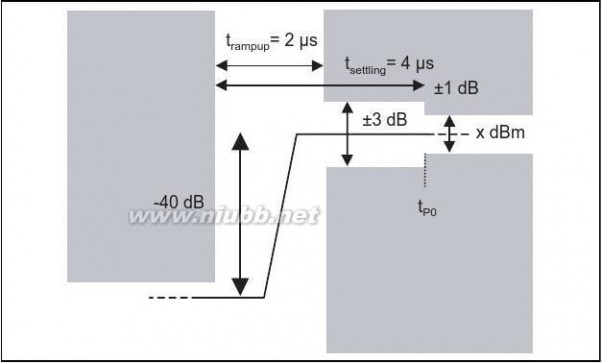
6221 March 2005Annex
rf2.0 RF_TS_EDR蓝牙测试规范2.0
BLUETOOTH TEST SPECIFICATION Ver. 1.2/2.0/2.0 + EDR [vol 2]Radio Frequencypage 63 of 726.1.2 3 Mbps Reference Signal (EDR)
A 3 Mbps Bluetooth signal used as "wanted" or "interfering signal" is defined as:
Modulation: 8DPSK
Symbol Rate = 1 Msym/s ±1 ppm
Frequency accuracy better than ±1 ppm
Modulating Data for wanted signal = PRBS9
Modulating Data for interfering signal = PRBS15
RMS Differential Error Vector Magnitude < 5%
Average power over the GFSK and DPSK portions of the packet shall
be equal to within ±1 dB
6.2 PROVISIONAL RF TESTING (EDR)
Measurement of RF performance in accordance with the RF test cases may not be possible until appropriate test equipment, with loop back capability, is available. Therefore, certain deviations from the specified test procedures shall be permitted for an interim period. These deviations cease to be permit-ted for a particular test case when this test case is made active in Category A as indicated in a released Test Case Reference List (TCRL).
The permitted test procedure deviations are as follows:
?Non loop back testing may be used.
?The EUT may be configured for a test case by any suitable means.?Whitening may be disabled.
?Frequency hopping may be disabled.
?For receiver bit error measurements, the bit error rate may be calculated and reported by any suitable means.
For each test case, all deviations from the specified test procedure shall be documented by the manufacturer.
6.3 FREQUENCIES FOR TESTING
6.3.1 Operating frequency bands
The Bluetooth system is operating in the 2.4 GHz ISM band. .
6.3.2 Frequencies for testing, loopback, hopping off
Several test cases of this RF Test Specification make use of the Bluetooth test-mode, loopback with hopping turned off. These test cases reference to this Annex21 March 200563
rf2.0 RF_TS_EDR蓝牙测试规范2.0
BLUETOOTH TEST SPECIFICATION Ver. 1.2/2.0/2.0 + EDR [vol 2]Radio Frequency
page 64 of 72
Regulatory Range2.400-2.4835 GHz
RF Channels used by Bluetooth
f =2402+k MHz, k = 0,…,78
Table 6.1: Operating frequency bands
section and the EUT's receive and transmit frequencies are set according Table 6.2 on page 64 and Table 6.3 on page 64: For transmit test cases:
Low operating frequencyEUT fTX2402 MHz
EUT fRX2480 MHz
Mid operating frequencyEUT fTX12441 MHz
EUT fRX12402 MHz
High operating frequencyEUT fTX2480 MHz
EUT fRX2402 MHz
Table 6.2: Frequencies for transmit test cases
For receive test cases:
Low operating frequencyEUT fTX2480 MHz
EUT fRX2402 MHz
Mid operating frequencyEUT fTX2402 MHz
EUT fRX2441 MHz
High operating frequencyEUT fTX2402 MHz
EUT fRX2480 MHz
Table 6.3: Frequencies for receive test cases
6.3.3 Frequencies for testing, TX-Test, hopping off
Some test cases of this RF Test Specification make use of the Bluetooth test-mode, TX-test, with hopping turned off. These test cases reference to this sec-tion and the EUT's transmit frequencies are set according Table 6.4 on page 65:
6421 March 2005Annex
rf2.0 RF_TS_EDR蓝牙测试规范2.0
BLUETOOTH TEST SPECIFICATION Ver. 1.2/2.0/2.0 + EDR [vol 2]Radio Frequencypage 65 of 72Low operating
frequency
EUT fTX
2402 MHzMid operating frequencyEUT fTX2441 MHzHigh operating frequencyEUT fTX2480 MHz
Table 6.4: Frequencies TX-test, hopping off
6.4 NORMAL TEST CONDITIONS
All test cases must be performed under the following normal test conditions.
6.4.1 Normal temperature and humidity
The normal temperature and humidity conditions for tests shall be any conve-nient combination of temperature and humidity within the following ranges:?temperature: +15°C to +35°C
扩展:蓝牙rf性能测试规范 / 蓝牙2.1 edr / 蓝牙edr
?relative humidity: 20 % to 75 %
The actual values during the tests shall be recorded in the test report.
When it is impracticable to carry out the tests under these conditions, a note to this effect, stating the ambient temperature and relative humidity during the tests, shall be recorded in the test report.
6.4.2 Nominal Power sourceThe nominal test voltage for equipment to be connected to the mains shall be the nominal mains voltage. The nominal voltage shall be declared voltage or any of the declared voltages for which the equipment was designed. The fre-quency of the test power source corresponding to the AC mains shall be within 2% of the nominal frequency.Annex21 March 200565
rf2.0 RF_TS_EDR蓝牙测试规范2.0
BLUETOOTH TEST SPECIFICATION Ver. 1.2/2.0/2.0 + EDR [vol 2]Radio Frequencypage 66 of 72When radio equipment is intended for operation from usual, alternator fed lead-acid battery power sources used on vehicles, then the nominal test voltage shall be 1,1 times the nominal voltage of the battery (6V, 12V, etc.)For operation from other power sources or types of battery (primary or second-ary), the nominal test voltage shall be as declared be the equipment manufac-turer. This shall be recorded in the test report.
6.5 EXTREME TEST CONDITIONS
6.5.1 Extreme temperatures
The extreme temperature range is defined as the largest temperature range given by the combination of
?The minimum temperature range 0 °C to +35 °C
?The product operating temperature range declared by the manufacturer.
This extreme temperature range and the declared operating temperature range shall be recorded in the test report.
6.5.2 Extreme power source voltages
Tests at extreme power source voltages specified below are not required when the equipment under test is designed for operation as part of and powered by another system or piece of equipment. Where this is the case, the limit values of the host system or host equipment shall apply. The appropriate limit values shall be declared by the manufacturer and recorded in the test report.The extreme test voltage for equipment to be connected to an AC mains source shall be the nominal mains voltage ±10%.When radio equipment is intended for operation from the usual type of alterna-tor fed lead-acid battery power source used on vehicles, then extreme test volt-age shall be 1.3 and 0.9 times the nominal voltage of the battery (6V, 12V etc.)6621 March 2005Annex
rf2.0 RF_TS_EDR蓝牙测试规范2.0
BLUETOOTH TEST SPECIFICATION Ver. 1.2/2.0/2.0 + EDR [vol 2]Radio Frequencypage 67 of 72The lower extreme test voltage for equipment with power sources using the fol-lowing types of battery, shall be:
a)for Leclanché, alkaline, or lithium type battery: 0.85 times the
nominal voltage of the battery
b)for the mercury or nickel-cadmium types of battery: 0.9 times the
nominal voltage of the battery.
In both cases, the upper extreme test voltage shall be 1.15 times the nominal voltage of the battery.For equipment using other power sources, or capable of being operated from a variety of power sources (primary or secondary), the extreme test voltages shall be those declared by the manufacturer; these shall be recorded in the test report.
6.6 BIT ERROR RATE (BER) MEASUREMENTS
BER measurements are carried out by comparing data in the payload fields transmitted by the tester with data in the payload fields received from the EUT. If the tester does not support the loop back method of measuring BER for 2 Mbps or 3 Mbps, it is allowed to use an alternative measurement method as specified in Section 6.2.
Payload as used in this Test Specification will mean the EUT transmitted data. Only Payload data is counted for the BER measurement. The Payload header and Payload CRC are ignored.
If the EUT is unable to loop back a packet (e.g. sync not found or header check fails), this packet shall be disregarded from the BER measurement. The EUT shall regenerate the payload CRC based on the actual received payload bits.Let the number of payload bits counted in error be γ , let the number of payload bits received (via loop back) from the EUT be ξ, then:
For BER sensitivity testing and floor testing an Early Exit option applies. If the early exit option is exercised the required number of bits (ξ) and BER Limit are given in Table6.5 and Table6.6

.
Annex21 March 200567
rf2.0 RF_TS_EDR蓝牙测试规范2.0
BLUETOOTH TEST SPECIFICATION Ver. 1.2/2.0/2.0 + EDR [vol 2]Radio Frequencypage 68 of 72BER Limit
7?10-57?10-6ξ1 600 0008 000 000
Table 6.5: Number of Bits for BER Limit with Early Exit
For the following BER limits the following values of ξ shall apply:BER Limit
10-3
扩展:蓝牙rf性能测试规范 / 蓝牙2.1 edr / 蓝牙edr
10-4
10-5ξ1 600 00016 000 000160 000 000
Table 6.6: Number of Bits for BER Limit without Early Exit
6821 March 2005Annex
rf2.0 RF_TS_EDR蓝牙测试规范2.0
BLUETOOTH TEST SPECIFICATION Ver. 1.2/2.0/2.0 + EDR [vol 2]Radio Frequencypage 69 of 726.7 DEFINITION OF THE POSITION OF BIT p0
The start of bit p0, which is the first preamble bit, is defined to occur at the point in time 68 bit periods before the instant at which the modulated carrier passes through the nominal channel frequency immediately prior to the deviation cor-responding to the first bit of the Access Code trailer for the EUT as defined in the Baseband Specification 4.2.
The position of the start of bit p0 is calculated using an averaging based on the position of all the zero crossings in the packet:
For the m zero crossings in the packet, the i'th zero crossing time is t(i) in μs; this is the start of bit p(i).
(1 <= i <= m ).
The start of bit p0 is then:
with bit time is 1μs.
6.8 DEFINITION OF THE REFERENCE SENSITIVITY LEVELThe reference sensitivity level is defined as –70 dBm.
6.9 ANTENNA GAIN
If it is necessary for Regulatory test purposes the TX peak antenna gain shall be used and declared by the manufacturer.
6.10 MEASUREMENT UNCERTAINTY
The following values of measurement uncertainty associated with each mea-surement parameter apply to all of the test cases described in this RF Test Specification.
6.10.1 Conducted measurements:
?Absolute RF power (wanted channel) 1: ± 1.2 dB
?Absolute RF power (for unwanted emissions in the BT band) 1: ± 3 dB
?Absolute RF power (for unwanted emissions outside the BT band) 1: ± 3 dB (4 dB)
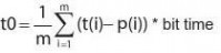
2
Annex21 March 200569
rf2.0 RF_TS_EDR蓝牙测试规范2.0
BLUETOOTH TEST SPECIFICATION Ver. 1.2/2.0/2.0 + EDR [vol 2]Radio Frequencypage 70 of 726.10.2 Relative RF power
?Relative RF power1: ± 1 dB
6.10.3 Radiated measurements
?Absolute RF power (wanted channel) 1: ± 6dB
?Radiated emissions (for unwanted emissions)1: ± 6dB
6.10.4 Absolute radio frequency
?Absolute radio frequency: ± 5 kHz
6.10.5 Relative drift radio frequency
?Relative drift radio frequency: ± 1 kHz
6.10.6 Peak frequency deviation
?Peak frequency deviation: ± 4 kHz
“The measurement uncertainties of the used measurement equipment must be equal or better as described above. The verdicts of the TCs consider already these measurement uncertainties.”
NOTE: All figures reflect a 95 % confidence level.
Note 1: All values are tentative.
Note 2: 4 dB for frequencies above 4 GHz.
The values include the mismatch between the measurement equipment and the EUT or antenna gain uncertainty of the measurement equipment.
6.11 TEST CASE MAPPING
The test case mapping list shown below determines which test case is applica-ble depending on the supported features. The “support” column has to be filled out according to the supported feature. The feature list with their item numbers is derived from the PICS proforma for Radio (RF) document which includes the IXIT table as well. If a feature is supported according to the logical connection under “item”, the corresponding test case has to be performed.
For purpose and structure of the PICS/proforma and instructions for completing the PICS/PIXIT proforma refer to the Bluetooth PICS-PIXIT Proforma docu-ment.
7021 March 2005Annex
rf2.0 RF_TS_EDR蓝牙测试规范2.0
BLUETOOTH TEST SPECIFICATION Ver. 1.2/2.0/2.0 + EDR [vol 2]Radio Frequencypage 71 of 72ItemFeatureSupportTest Case
Output Power
TRM/CA/01/C
Power Density
TRM/CA/02/CTest Case ApplicableYesYes
RF, 1/2Power ControlPower Control
TRM/CA/03/C
TX Output Spec-
trum - Frequency
Range
TRM/CA/04/C
TX Output Spec-
trum - 20 dB Band-
width
TRM/CA/05/C
TX Output Spec-
trum - Adjacent
channel power
TRM/CA/06/C
Modulation Charac-
teristics
TRM/CA/07/C
Initial Carrier Fre-
quency Tolerance
TRM/CA/08/C
Carrier Frequency
Drift
TRM/CA/09/C
Sensitivity (single
slot packets)
RCV/CA/01/CYesYesYesYesYesYesYes
RF, 1/4
OR
RF, 1/53 or 5 slot packetsSensitivity (multi slot packets)RCV/CA/02/C
C/I Performance
RCV/CA/03/C
Blocking Perfor-
mance
RCV/CA/04/C
Intermodulation
Performance
RCV/CA/05/CYesYesYes
Table 6.7: Test Case Mapping
Annex21 March 200571
rf2.0 RF_TS_EDR蓝牙测试规范2.0
BLUETOOTH TEST SPECIFICATION Ver. 1.2/2.0/2.0 + EDR [vol 2]Radio Frequency
扩展:蓝牙rf性能测试规范 / 蓝牙2.1 edr / 蓝牙edr
page 72 of 72
ItemFeatureSupportTest CaseMaximum Input Level
RCV/CA/06/C
Test Case ApplicableYes
RF, 1/8ORRF, 1/9RF, 1/8ORRF, 1/9
EDR Relative Transmit Power
EDR RF Accuracy
EDR Relative Transmit PowerTRM/CA/10/CEDR Carrier Fre-quency Stability and Modulation Accu-racy
TRM/CA/11/CEDR Differential Phase EncodingTRM/CA/12/CEDR In-band Spuri-ous EmissionsTRM/CA/13/CEDR SensitivityRCV/CA/07/CEDR BER Floor PerformanceRCV/CA/08/CEDR C/I Perfor-mance
RCV/CA/09/CEDR Maximum Input LevelRCV/CA/10/C
RF, 1/8ORRF, 1/9RF, 1/8ORRF, 1/9RF, 1/8ORRF, 1/9RF, 1/8ORRF, 1/9RF, 1/8ORRF, 1/9RF, 1/8ORRF, 1/9
EDR Differential Phase Encoding
EDR In-Band Spurious Emissions
EDR Sensitivity Level for 10-4 BER
EDR Sensitivity Level for 10-5 BER
EDR Interference Per-formance
EDR Maximum Usable Input Signal Level
Table 6.7: Test Case Mapping
7221 March 2005Annex
扩展:蓝牙rf性能测试规范 / 蓝牙2.1 edr / 蓝牙edr
本文标题:合作规范2.0版-推荐:最新RSS 2.0规范(中文版)大全61阅读| 精彩专题| 最新文章| 热门文章| 苏ICP备13036349号-1