一 : Experimental research on seismic performance of K-style s
Structures Congress 2013 ? ASCE 20132802
Experimental research on seismic performance of K-style steel outrigger truss to
concrete core tube wall joints
Jianguo Nie1 and Ran Ding1
1
erved.Key Laboratory of Civil Engineering Safety and Durability of China Education Ministry, Department of Civil Engineering, Tsinghua University, Beijing 100084, China; email: dingran1988@163.com ABSTRACT
Since outriggers play an important role in the structure system, the outrigger truss -
core tube joint is surely a key point which has a significant effect on the seismic
performance of tall buildings. This paper presents experimental study on the seismic
behavior of K-style steel outrigger truss to concrete core tube wall joints. Two
specimens with different details of the joint, including joint with outside steel plate and
encased steel plate, were tested under cyclic vertical loads on column ends. Several
indexes that could reflect the seismic performance of the composite joint, such as the
strength degradation, the rigidity degradation, ductility and the energy dissipation
capacity were analyzed. It was found that the composite joints could transfer the load
reliably and exhibited favorable seismic performance. It was also concluded that the
joint with outside steel plate was better than that with encased steel plate with more
construction convenience, higher buckling load and less concrete cracks.
Keywords: outrigger truss; core tube; joint details; seismic behavior; outside steel plate
1. INTRODUCTION
High-rise and super high-rise buildings are being widely used in recent years in
China (Wang and Zhou 2010). For the structural design of these buildings, the control
of top drift and base moment in the core under lateral loads are the key problems. As
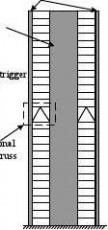
shown in Fig.1, the core tube – frame – outrigger truss system is regarded as one of the
most effective ways to solve the problem and has been widely applied in tall building
structures (Wu and Li 2003).
Since outriggers play an important role in the structure system, the outrigger truss -
core tube joint is surely a key point which has a significant effect on the seismic
performance of tall buildings. Therefore, it is necessary to investigate the seismic
performance of the connection both experimentally and numerically. Park (1982),
Shahrooz (1993) and Park and Yun (2005) studied the seismic behavior of steel beam to
concrete wall joints and paid special attention to the calculation of embedded length of
the steel beams. Shahrooz et al. (2004a, b) studied the performance of outrigger beam –
core wall connections with headed studs that are typically used to connect a stud plate,
onto which the outrigger beam is connected through a shear tab, to the wall. A new
design technique was developed and the performance based on the new methodology
was found to be better.
Structures Congress 2013 Downloaded from ascelibrary.org by HUNAN UNIVERSITY on 10/10/13. Copyright ASCE. For personal use only; all rights res
Structures Congress 2013 ? ASCE 20132803
erved.As shown in Fig. 1, when the structure is subject to horizontal loadings, compared to the conventional outrigger truss, the upper and lower web members of the K-style truss are under tension and compression, respectively. The horizontal components are thus balanced and the shearing forces of the perimeter columns are thus vanished. With this advantage, the K-style truss has been widely used recently (Lei et al. 2011; Zhou et al. 2012). The sections of upper and lower web members in the K-style outrigger trusses which are subject to large axial force and bending moment, are usually very large. The joints of trusses and core tube wall are thus more complicated and important than those
of steel beams and core tube wall. Therefore, it is very necessary to investigate the
seismic performance and loading transfer mechanism of the joint and simplify the joint
details to improve construction convenience. Ma et al. (2009) conducted a finite element
analysis (FEA) on the seismic performance of K-style truss to core tube wall joint.
However, the key problems in the design and application of the K-style truss to core
tube wall joint mentioned above are lacking of research and no tests have been reported
in the literature up to now.
In the present study, two specimens were tested under cyclic loads with different
details, including joint with outside steel plate and encased steel plate. Several indexes
that could reflect the seismic performance of the composite joint, such as the strength
degradation, the rigidity degradation, the ductility and the energy dissipation capacity
were then analyzed. The seismic performance of these two kinds of joint was compared.
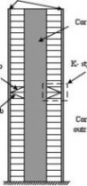
Perimeter column
(a) K-style truss(b) Conventional truss
Fig. 1 Schematic view of outrigger trusses in tall buildings
2. EXPERIMENTAL PROGRAM
2.1 Design of test specimens
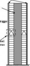
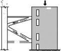
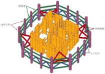
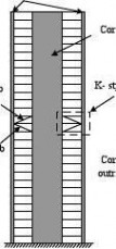
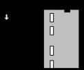
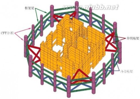
Fig. 2(a) shows a schematic drawing of the structure of a high-rise building and the
strengthened story. The concrete filled steel tubular (CFST) columns around are
Structures Congress 2013 Downloaded from ascelibrary.org by HUNAN UNIVERSITY on 10/10/13. Copyright ASCE. For personal use only; all rights res
Structures Congress 2013 ? ASCE 20132804
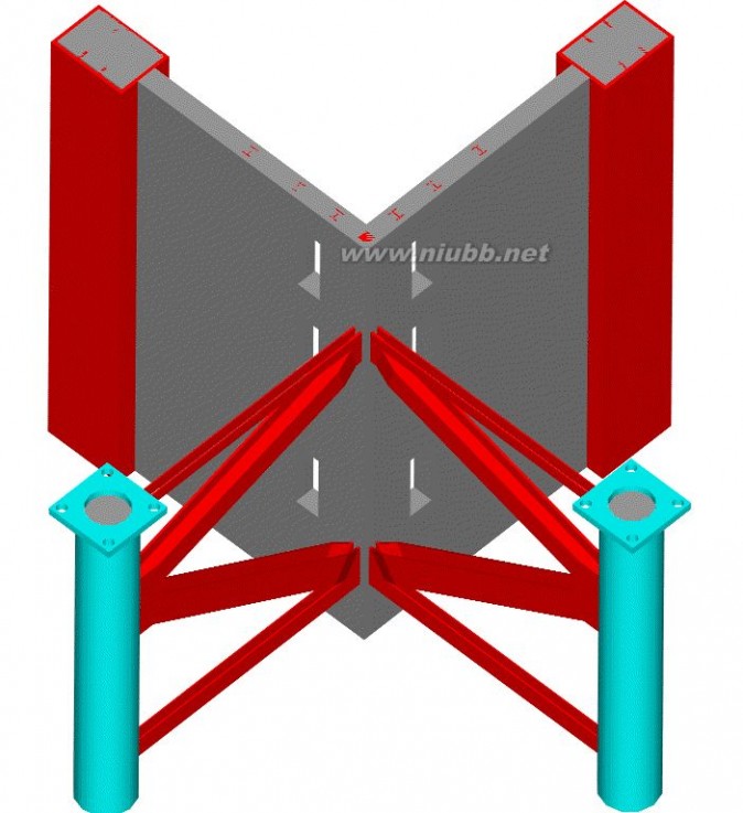
erved.connected to the core tube by the K-style outrigger trusses with frame beams and belt trusses around. As shown in Fig. 2(b), the outrigger truss to core tube joint is selected to be the test specimens. The joint consists of two pieces of outrigger trusses at the corner of the core tube and the corresponding walls. Since the frame beams and belt trusses have little influence on the performance of the joint, they are not included in the test specimens. A scale factor of approximately 1/8 is chosen to establish the specimen considering the loading capacity of the test apparatus and space of the laboratory. The loading conditions of the joint are presented in Fig. 2(c). In the figure, P represents the
load caused by the horizontal earthquake or wind and N refers to the vertical load


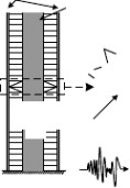


transferred from the upper floors.
Fig. 2 Schematic view of joint models in a real structure
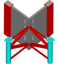
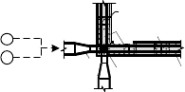
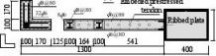
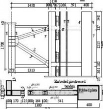
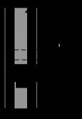
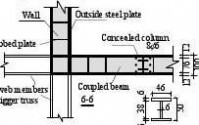
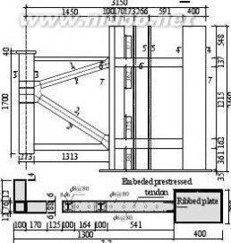
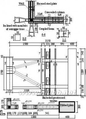
As shown in Fig. 2(b), the main experimental parameters investigated are the details
of the joint, including joint with encased steel plate and outside steel plate. In the joint
with encased steel plate (OTJ-2), the web members of the outrigger truss are necked and
welded to the embedded steel reinforcement of the wall, which is then connected to two
steel plates embedded into the wall. On the other hand, in the joint with outside steel
plate (OTJ-1), the web members keep the same width and welded to the steel plate
outside the wall. The steel plates from two directions form a rectangular CFST column
at the corner of the wall. Fig. 3 shows the configurations of both specimens.
2.2 Material properties
Tension tests were carried out to determine the material properties of steel plates
and reinforcements. The yield strength (fy), the ultimate strength (fu) and the elongation
ratio of steel (δ) are listed in Table 1, respectively. The compressive strength of 150mm
size cubes at the age of 28 days for the concrete used to fill the steel tubes and form the
wall was tested. The cubic compressive strength (fcu) is 42.2 MPa and 44.6MPa for
specimen OTJ-1 and OTJ-2, respectively.
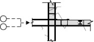
2.3 Loading apparatus and measurements
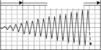
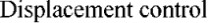
Fig. 4 gives a general view of the test setup. Cyclic loads (P) in vertical direction
Structures Congress 2013 Downloaded from ascelibrary.org by HUNAN UNIVERSITY on 10/10/13. Copyright ASCE. For personal use only; all rights res
Structures Congress 2013 ? ASCE 20132805
were applied at the ends of the two circular CFST columns synchronously. The axial compressive load N was applied on the top of the wall by prestressed tendons. In the beginning of the test, all the prestressed tendons were tensioned to the expected level. Then the vertical column loads P were applied cyclically in small increments until failure of the composite joint. The loading history consists of a force control stage followed by a displacement control stage, as shown in Fig. 5.
erved.
2.4 Measurements
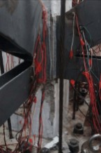
Fig. 6 shows the arrangement of measuring equipment. The loads at the column ends were measured by load cells. Dial indicators were used to measure the displacement of columns and walls. Strain gauges were arranged on the steel truss, ending column, outside (encased) steel plate and concrete wall to measure the strain distributions.


1-12-2
3-3
4-4
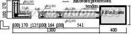
(a) OTJ-1(b) OTJ-2
Fig. 3 Configuration of the joint specimens (unit: mm)
Table 1 Material properties of steel and reinforcement
Components
t or d fy fu (mm)
(MPa)
(MPa)
δ
Structures Congress 2013
Downloaded from ascelibrary.org by HUNAN UNIVERSITY on 10/10/13. Copyright ASCE. For personal use only; all rights res
Structures Congress 2013 ? ASCE 20132806
erved.Web of truss members Part of ending column at the corner of wall Circular steel tube Flange of truss members Outside (encased) steel plate Longitudinal steel bar in the wall Stirrups of the concealed columns 5 300.2 57.6 3.5 6 298.7 38.7 35.7 8 35.6 72.8 3.3 12 316.9 434.6 39.9 12 316.9 434.6 39.9 367.3 549.3 - Φ 6 284.8 489.7
- Φ 8
Rigid frameHydraulic jack
Lateral bracePrestressed tendon
CFST column)y


)/

Corner tendonsyP(


/t


Pn

(e

d
am

oeLc

a

lp

si

DOutrigger trussWall
North


Base beam
444
4
Fig. 4 A general view of the test set-up Fig. 5


Schematic view of loading history 44
Fig. 6 Main measuring points arrangement
Structures Congress 2013 Downloaded from ascelibrary.org by HUNAN UNIVERSITY on 10/10/13. Copyright ASCE. For personal use only; all rights res
Structures Congress 2013 ? ASCE 20132807
3 EXPERIMENTAL RESULTS
Some of the measured experimental results are summarized in Table 2, where, Py(+)
and Py(-) are the yield load of the joint under tensile and compressive vertical load,
respectively; Pmax is the maximum load of the joint, respectively; μ is the displacement
ductility coefficient, which is defined as Δu/Δy, where Δu is defined as the maximum
displacement corresponding to the load no less than 0.85Pmax; he is the equivalent
damping ratio. erved.
Table 2 Summary of the measured results
Specimen Truss Py(kN) Pmax(kN) Δy(mm) Δu(mm) μ
segment (+) (-) (+) (-) (+) (-) (+) (-) (+) (-) he
OTJ-1 East 760.2 697.
923.6 823.0 19.7 17.8 5.0 2.9 2.7 2.0 0.225

South 70.8 892.6 900.3 1039.1 17. 19.7 5. 36. 3.13 1.85 0.23
OTJ-2 East 735.1 735.1 860.7 823.0 17.8 18.3 8. 38.7 2.71 2.11 0.198
South 709.9 885.9 848.2 936.1 20.2 18.3 44
.7 38.2 2.22 2.09 0.200
444444
1200

1200


900900
600
600300300
00
-300-300-600-600-900-900-1200-60-45-30-15015304560-1200
/mm-60-45-30-15/0mm15304560
(a) OTJ-1 (east truss)(b) OTJ-1 (south truss)
12001200900900600600
30030000
-300-300
-600-600
-900-900-1200-60-45-30-15015304560-1200/mm/mm
(c) OTJ-2 (east truss)(d) OTJ-2 (south truss)
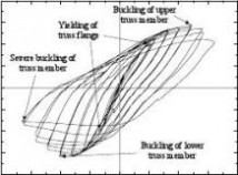
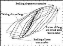
Fig. 7 Measured P-Δ hysteretic relations
Structures Congress 2013 Downloaded from ascelibrary.org by HUNAN UNIVERSITY on 10/10/13. Copyright ASCE. For personal use only; all rights res


Structures Congress 2013 ? ASCE 20132808
P/k


N
P/k


N


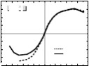
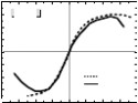
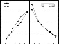
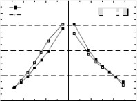
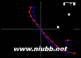
erved.Fig. 8 P-Δ skeleton curves under different parameters
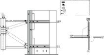
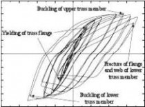
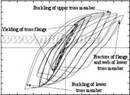
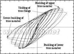
The P-Δ hysteretic curves of the trusses are presented in Fig.7. The skeleton curves
were obtained by connecting the peak points on the measured hysteretic curves together.
The skeleton curves so determined with different truss segments and joint details are
shown in Fig. 8
. OTJ-2
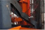
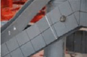
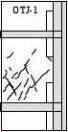
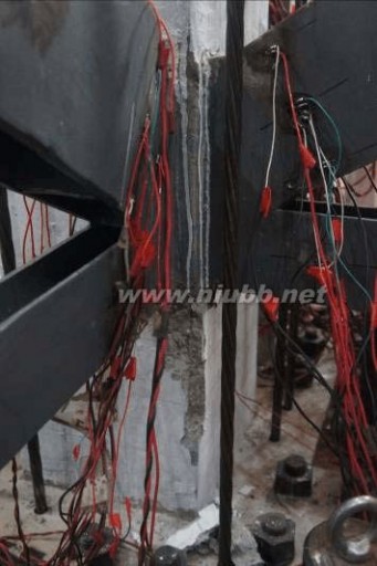
(a) Cracking pattern(d) Spalling of concrete at joint region(OTJ-2)
(b) Truss buckling of OTJ-1(e) Plate deformation at joint necking region(OTJ-2)
(c) Flange rupture of OTJ-1(f) Truss buckling of OTJ-2
(OTJ-1)
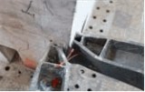

(OTJ-2)
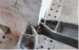
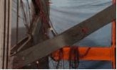
Fig. 9 Failure phenomena of joint specimens
(1) Specimen OTJ-1
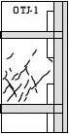
Two visible inclined cracks were observed on the wall between the two outside steel
plates at the load of P=+0.75Py.The largest width of the concrete diagonal cracks was
approximately 0.2mm at 1.5Δy. Fig. 9(a) shows the distribution of cracks for specimen
OTJ-1. At the load of P = Py, the outrigger truss section experienced a yielding at this
moment while the joint zone was far from yielding. At the loading stages of 3.5Δy, the
Structures Congress 2013 Downloaded from ascelibrary.org by HUNAN UNIVERSITY on 10/10/13. Copyright ASCE. For personal use only; all rights res
Structures Congress 2013 ? ASCE 20132809
lower member suffered a severe overall buckling with local buckling of flanges as
shown in Fig. 9(b). One of the flanges of lower member were completely fractured at
the second cycle of 4.5Δy and the web nearby were partly fractured, as shown in Fig.
9(c).
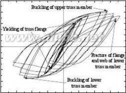
(2) Specimen OTJ-2
erved.As shown in Fig. 9(a), more cracks which appeared earlier were observed for specimen OTJ-2 than specimen OTJ-1. The directions were similar to those observed
for specimen OTJ-1 while the largest width of the concrete diagonal cracks was larger
with approximately 0.3mm at 1.5Δy. The spalling of large amount of concrete on the
wall below the lower joint plate was observed and the spalling region occupied nearly
all over the wall below the lower joint plate, as shown in Fig. 9(d). At the load of P = Py
and -Py, the outrigger truss section experienced a yielding while the joint zone was far
from yielding, which is similar to specimen OTJ-1.Slight overall buckling was observed
on the lower member at -2.5Δy, which was earlier than that of specimen OTJ-1. Obvious
lateral distortion of the plate at the necking region was observed, as shown in Fig. 9(e).
At the loading stages of 4Δy and -4Δy, the load reached 85% of the ultimate bearing
capacity and severe damage of truss members were shown in Fig. 9(f).
4 ANALYSIS OF EXPERIMENTAL RESULTS
4.1 Load versus displacement relations
Fig. 7 plots the load-displacement hysteretic relations at the columns ends for both
specimens. It can be seen that the P-Δ curves for the two joints and different column
ends are similar in the overall outline, which look ‘plump’ indicating that they have
good energy dissipation capacity.
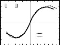
As shown in Fig. 8, the load-displacement skeleton curves looks like a letter ‘S’,
indicating that the joint exhibits three different stages under the cyclic loads which
include elastic, plastic and ultimate failure. The P-Δ skeleton curves for the two
different column ends are almost the same when subjected to tensile force and
moderately different when subjected to compressive force. This could be explained by
the different initial imperfections measured for the lower truss members. The initial
imperfections for the east lower truss members are larger than the south ones so the
buckling capacity is lower.
4.2 Strength degradation
The strength degradation coefficient (λj) versus displacement (Δ/Δy) for both
specimens is shown in Fig. 10. λj is used to illustrate the degradation, which is defined
by Han and Li (2010). It can be seen from the figure that the coefficient λj is generally
smaller than 1 meaning that the strength of the joints is degrading with the loading
repeated. The strength degradation is found to be decreasing with the increase of
Structures Congress 2013 Downloaded from ascelibrary.org by HUNAN UNIVERSITY on 10/10/13. Copyright ASCE. For personal use only; all rights res
Structures Congress 2013 ? ASCE 20132810
displacement level generally. As shown in Fig. 10(a), λj decreases rapidly for the south
truss after the fracture of the lower member.
4.3 Rigidity degradation
The index of cyclic rigidity (Kl) is used to describe the degradation of the rigidity,
which is defined by Nie et al. (2008a). Fig.11 shows the cyclic rigidity Kl versus
displacement relationship of the joints. It can be found from the figure that Kl for the
south truss is generally larger than those for the east truss when subjected to erved.
compressive force while they are almost the same when subjected to tensile force.
Similar to the illustration of bearing capacity, this could be explained by the different
initial imperfections for the lower truss members. The initial imperfections for the east
lower truss members are larger than the south ones so the rigidity is lower. It can also be
seen that Kl of the truss under compression were smaller and exhibited a quicker
decrease than those of the same one under tension. This is due to the fact that the truss


under compression suffered a more severe and earlier buckling than those under tension.


jj


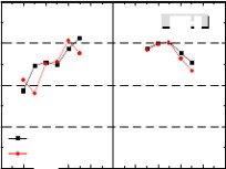
Fig. 10


Strength degradation of specimens
mmm


m


//
NN
kk
ll
KK
Fig. 11 Rigidity degradation of specimens
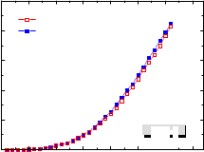
4.4 Energy dissipation
The energy dissipation capacity of the joints could be evaluated by the equivalent
damping coefficient (he) presented by Nie et al. (2008b). The calculated he for the cycle
Structures Congress 2013 Downloaded from ascelibrary.org by HUNAN UNIVERSITY on 10/10/13. Copyright ASCE. For personal use only; all rights res
Structures Congress 2013 ? ASCE 20132811
where the peak load appeared are listed in Table 2. It could be seen that he for the south
truss is slightly higher than those of the east truss for the same specimen. This is due to
the smaller initial imperfections of the south truss and thus plumper hysteretic response.
The total dissipated energy Etotal could also be used to describe the energy absorbing
capacity of the joints, which is obtained by accumulating the energy from each half
cycle. As shown in Fig. 12, for specimen OTJ-2, Etotal of the south truss is slightly
higher than that of the east truss; for specimen OTJ-1, Etotal of the south truss is
obviously higher than that of the east truss in the beginning and became lower finally. erved.
This contributes to the fact that after a severe buckling occurred, the displacement


loading level was reduced for the south truss.
m
.


m.


NNk/k/
lla
tatoottEE
Fig. 12 Energy consumed versus number of half cycles
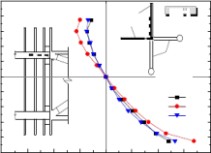
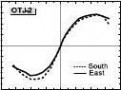
4.5 Analysis of strain and cracks
Fig. 13 presents the strain response on the encased steel plate. In the figure, strain
gauge 1 lies nearest to the joint where the height of steel plate is larger; Strain gauge 2
lies on the coupled beam where holes exist above and below; Strain gauge 3 lies furthest
from the joint. It can be seen that the steel plate is under compression with a positive
load and under tension with a negative load. The compressive strain is obviously
smaller than the tensile strain, which contributes to the fact that concrete has a good
compressive capacity and a poor tensile capacity. The strain gauge 2 exhibits a lager
strain than the other two gauges because of the larger height of steel plate for gauge 1
and larger distance from the joint for gauge 3.
Fig. 9(a) shows the cracking pattern of the wall for both specimens. The diagonal
cracks are caused because the wall is under shear due to the reverse tensile force and
compressive force of the upper and lower steel plate in the wall. The angles between the
diagonal cracks and horizontal direction are a little larger than 45° due to the change of
the principle tensile stress direction of the concrete subjected to the axial load. It is thus
concluded that the concrete wall between the upper and lower steel plate acts like a
diagonal strut.
Structures Congress 2013 Downloaded from ascelibrary.org by HUNAN UNIVERSITY on 10/10/13. Copyright ASCE. For personal use only; all rights res


Structures Congress 2013 ? ASCE 20132812
erved.P/k


N
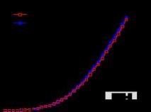
Fig. 13 Load-strain curves of encased steel plate (specimen OTJ-2)
4.6 Influence of different joint details
It was observed that the joint detail has a moderate effect on the P-Δ curve. The
stiffness and maximum load of specimen OTJ-1 are slightly higher than those of
specimen OTJ-2 while the displacement corresponding to the maximum load of
specimen OTJ-1 is obviously larger. The ductility coefficient μ and equivalent damping
coefficient he for OTJ-1 are larger than those for OTJ-2. This is due to the fact that the
section of the truss members near the wall became narrow for specimen OTJ-2, then the
buckling capacity and stiffness were reduced and buckling occurred earlier. It could also
be seen that the cracking of the wall is more severe for specimen OTJ-2, such as the
spalling of large amount of concrete on the wall below the lower joint plate and
horizontal cracks on the wall where encased steel plate exists. This contributes to the
fact that the steel plate of specimen OTJ-1 is placed outside the wall and the cracks are
thus invisible. It could be observed from the reinforcement details and the preparation of
both specimens that OTJ-1 is much more convenient to construct than OTJ-2 since the
steel plate is outside the wall, the number of steel bars is thus reduced and concrete are
cast more easily.
5 CONCLUSIONS
The following conclusions can be drawn based on the experimental evaluations
within the limitations of the research presented in this paper:
(1). Generally, the failure mode of the joints is the elasto-plastic buckling of the
truss members. It was observed that the tested specimens behaved in a relatively ductile
manner. The experimental results presented in this paper show that these two joints
have a prospect to be applied in seismic region.
(2). It was found from the experimental results that the seismic performance of
specimen OTJ-1 with outside steel plate is better than those of specimen OTJ-2 with
Structures Congress 2013 Downloaded from ascelibrary.org by HUNAN UNIVERSITY on 10/10/13. Copyright ASCE. For personal use only; all rights res
Structures Congress 2013 ? ASCE 20132813
encased steel plate. The stiffness and maximum load of specimen OTJ-1 is slightly
larger than that of OTJ-2 while the displacement corresponding to the maximum load of
specimen OTJ-1 is obviously larger. It could also be seen that the cracking of the wall is
more severe for specimen OTJ-2.
(3). It could be observed from the reinforcement details and the preparation of both
erved.specimens that specimen OTJ-1 is much more convenient to construct than specimen OTJ-2 since the steel plate is outside the wall, the number of steel bars is thus reduced and concrete are cast more easily.
ACKNOWLEDGMENTS
The writers gratefully acknowledge the financial support provided by "Twelfth
Five-Year" plan major projects supported by National Science and Technology (Grant
No. 2011BAJ09B01) and Tsinghua University Initiative Scientific Research Program
(Grant No. 2010Z03078).
REFERENCES
Han, L.H., and Li, W. (2010). “Seismic performance of CFST column to steel beam joint with RC slab:
Experiments.” J. Constr. Steel Res., 66(11), 1374-1386.
Lei, Q., Liu, G.Y., and Hou, S.L. (2011). “Structural preliminary design of exceed-limit high-rise building
of Kingkey Financial Center.” Build. Struct., 41(S1), 346-351(in Chinese).
Ma, C.J., Zhang, L.P., and Fan, Z. (2009). “Nonlinear finite element analysis on connection joint of a
super high-rise building.” Build. Struct., 39(9), 60-62(in Chinese).
Nie, J.G., Qin, K., and Cai, C.S. (2008a). “Seismic behavior of connections composed of CFSSTCs and
steel-concrete composite beams-experimental study.” J. Constr. Steel Res., 64(10), 1178-1191.
Nie, J.G., Bai, Y., and Cai, C.S. (2008b). “New Connection System for Confined Concrete Columns and
Beams. I: Experimental Study.” ASCE J. Struct. Eng., 134(12), 1787-1799.
Park, R., Priestley, M.J., and Gill, W.D. (1982). “Ductility of square confined concrete columns.” ASCE J.
Struct. Div., 108(4), 929-950.
Park, W.S., and Yun, H.D. (2005). “Seismic behavior of coupling beams in a hybrid coupled shear walls.”
J. Constr. Steel Res., 61(11), 1492-1524.
Shahrooz, B.M. (1993). “Seismic design and performance of composite coupled walls.” ASCE J. Struct.
Eng., 119(11), 3291-3309.
Shahrooz, B.M., Deason, J.T., and Tunc, G. (2004a). “Outrigger beam-wall connections. I: Component
testing and development of design model.” ASCE J. Struct. Eng., 130(2), 253-261.
Shahrooz, B.M., Tunc, G., and Deason, J.T. (2004b). “Outrigger beam-wall connections. II: Subassembly
testing and further modeling enhancements.” ASCE J. Struct. Eng., 130(2), 262-270.
Wang, D.S., and Zhou, J.L. (2010). “Development and prospect of hybrid high-rise building structures in
China.” J. Build. Struct., 31(6), 62-70 (in Chinese).
Wu, J.R., and Li, Q.S. (2003). “Structural performance of multi-outrigger-braced tall buildings.” Struct.
Design Tall Spec. Build., 12(2), 155–176.
Zhou, J., Chen, K., and Zhang, Y.F., et al. (2012). “Structural design on Wuhan Center Tower. Building
Structure.” Build. Struct., 42(5), 8-12(in Chinese).
Structures Congress 2013 Downloaded from ascelibrary.org by HUNAN UNIVERSITY on 10/10/13. Copyright ASCE. For personal use only; all rights res
二 : Experimental research on seismic performance of K-style steel outr
Structures Congress 2013 ? ASCE 20132802
Experimental research on seismic performance of K-style steel outrigger truss to
concrete core tube wall joints
Jianguo Nie1 and Ran Ding1
1
erved.Key Laboratory of Civil Engineering Safety and Durability of China Education Ministry, Department of Civil Engineering, Tsinghua University, Beijing 100084, China; email: dingran1988@163.com ABSTRACT
Since outriggers play an important role in the structure system, the outrigger truss -
core tube joint is surely a key point which has a significant effect on the seismic
performance of tall buildings. This paper presents experimental study on the seismic
behavior of K-style steel outrigger truss to concrete core tube wall joints. Two
specimens with different details of the joint, including joint with outside steel plate and
encased steel plate, were tested under cyclic vertical loads on column ends. Several
indexes that could reflect the seismic performance of the composite joint, such as the
strength degradation, the rigidity degradation, ductility and the energy dissipation
capacity were analyzed. It was found that the composite joints could transfer the load
reliably and exhibited favorable seismic performance. It was also concluded that the
joint with outside steel plate was better than that with encased steel plate with more
construction convenience, higher buckling load and less concrete cracks.
Keywords: outrigger truss; core tube; joint details; seismic behavior; outside steel plate
1. INTRODUCTION
High-rise and super high-rise buildings are being widely used in recent years in
China (Wang and Zhou 2010). For the structural design of these buildings, the control
of top drift and base moment in the core under lateral loads are the key problems. As
shown in Fig.1, the core tube – frame – outrigger truss system is regarded as one of the
most effective ways to solve the problem and has been widely applied in tall building
structures (Wu and Li 2003).
Since outriggers play an important role in the structure system, the outrigger truss -
core tube joint is surely a key point which has a significant effect on the seismic
performance of tall buildings. Therefore, it is necessary to investigate the seismic
performance of the connection both experimentally and numerically. Park (1982),
Shahrooz (1993) and Park and Yun (2005) studied the seismic behavior of steel beam to
concrete wall joints and paid special attention to the calculation of embedded length of
the steel beams. Shahrooz et al. (2004a, b) studied the performance of outrigger beam –
core wall connections with headed studs that are typically used to connect a stud plate,
onto which the outrigger beam is connected through a shear tab, to the wall. A new
design technique was developed and the performance based on the new methodology
was found to be better.
Structures Congress 2013 Downloaded from ascelibrary.org by HUNAN UNIVERSITY on 10/10/13. Copyright ASCE. For personal use only; all rights res
k-style Experimental research on seismic performance of K-style steel outrigger truss to
Structures Congress 2013 ? ASCE 20132803
erved.As shown in Fig. 1, when the structure is subject to horizontal loadings, compared to the conventional outrigger truss, the upper and lower web members of the K-style truss are under tension and compression, respectively. The horizontal components are thus balanced and the shearing forces of the perimeter columns are thus vanished. With this advantage, the K-style truss has been widely used recently (Lei et al. 2011; Zhou et al. 2012). The sections of upper and lower web members in the K-style outrigger trusses which are subject to large axial force and bending moment, are usually very large. The joints of trusses and core tube wall are thus more complicated and important than those
of steel beams and core tube wall. Therefore, it is very necessary to investigate the
seismic performance and loading transfer mechanism of the joint and simplify the joint
details to improve construction convenience. Ma et al. (2009) conducted a finite element
analysis (FEA) on the seismic performance of K-style truss to core tube wall joint.
However, the key problems in the design and application of the K-style truss to core
tube wall joint mentioned above are lacking of research and no tests have been reported
in the literature up to now.
In the present study, two specimens were tested under cyclic loads with different
details, including joint with outside steel plate and encased steel plate. Several indexes
that could reflect the seismic performance of the composite joint, such as the strength
degradation, the rigidity degradation, the ductility and the energy dissipation capacity
扩展:outrigger / outrigger konotta / outrigger酒店
were then analyzed. The seismic performance of these two kinds of joint was compared.
Perimeter column
(a) K-style truss(b) Conventional truss
Fig. 1 Schematic view of outrigger trusses in tall buildings
2. EXPERIMENTAL PROGRAM
2.1 Design of test specimens
Fig. 2(a) shows a schematic drawing of the structure of a high-rise building and the
strengthened story. The concrete filled steel tubular (CFST) columns around are
Structures Congress 2013 Downloaded from ascelibrary.org by HUNAN UNIVERSITY on 10/10/13. Copyright ASCE. For personal use only; all rights res
k-style Experimental research on seismic performance of K-style steel outrigger truss to
Structures Congress 2013 ? ASCE 20132804
erved.connected to the core tube by the K-style outrigger trusses with frame beams and belt trusses around. As shown in Fig. 2(b), the outrigger truss to core tube joint is selected to be the test specimens. The joint consists of two pieces of outrigger trusses at the corner of the core tube and the corresponding walls. Since the frame beams and belt trusses have little influence on the performance of the joint, they are not included in the test specimens. A scale factor of approximately 1/8 is chosen to establish the specimen considering the loading capacity of the test apparatus and space of the laboratory. The loading conditions of the joint are presented in Fig. 2(c). In the figure, P represents the
load caused by the horizontal earthquake or wind and N refers to the vertical load


扩展:outrigger / outrigger konotta / outrigger酒店


transferred from the upper floors.
Fig. 2 Schematic view of joint models in a real structure
As shown in Fig. 2(b), the main experimental parameters investigated are the details
of the joint, including joint with encased steel plate and outside steel plate. In the joint
with encased steel plate (OTJ-2), the web members of the outrigger truss are necked and
welded to the embedded steel reinforcement of the wall, which is then connected to two
steel plates embedded into the wall. On the other hand, in the joint with outside steel
plate (OTJ-1), the web members keep the same width and welded to the steel plate
outside the wall. The steel plates from two directions form a rectangular CFST column
at the corner of the wall. Fig. 3 shows the configurations of both specimens.
2.2 Material properties
Tension tests were carried out to determine the material properties of steel plates
and reinforcements. The yield strength (fy), the ultimate strength (fu) and the elongation
ratio of steel (δ) are listed in Table 1, respectively. The compressive strength of 150mm
size cubes at the age of 28 days for the concrete used to fill the steel tubes and form the
wall was tested. The cubic compressive strength (fcu) is 42.2 MPa and 44.6MPa for
specimen OTJ-1 and OTJ-2, respectively.
2.3 Loading apparatus and measurements
Fig. 4 gives a general view of the test setup. Cyclic loads (P) in vertical direction
Structures Congress 2013 Downloaded from ascelibrary.org by HUNAN UNIVERSITY on 10/10/13. Copyright ASCE. For personal use only; all rights res
k-style Experimental research on seismic performance of K-style steel outrigger truss to
Structures Congress 2013 ? ASCE 20132805
were applied at the ends of the two circular CFST columns synchronously. The axial compressive load N was applied on the top of the wall by prestressed tendons. In the beginning of the test, all the prestressed tendons were tensioned to the expected level. Then the vertical column loads P were applied cyclically in small increments until failure of the composite joint. The loading history consists of a force control stage followed by a displacement control stage, as shown in Fig. 5.
erved.
2.4 Measurements
Fig. 6 shows the arrangement of measuring equipment. The loads at the column ends were measured by load cells. Dial indicators were used to measure the displacement of columns and walls. Strain gauges were arranged on the steel truss, ending column, outside (encased) steel plate and concrete wall to measure the strain distributions.


扩展:outrigger / outrigger konotta / outrigger酒店
1-12-2
3-3
4-4
(a) OTJ-1(b) OTJ-2
Fig. 3 Configuration of the joint specimens (unit: mm)
Table 1 Material properties of steel and reinforcement
Components
t or d fy fu (mm)
(MPa)
(MPa)
δ
Structures Congress 2013
Downloaded from ascelibrary.org by HUNAN UNIVERSITY on 10/10/13. Copyright ASCE. For personal use only; all rights res
k-style Experimental research on seismic performance of K-style steel outrigger truss to
Structures Congress 2013 ? ASCE 20132806
erved.Web of truss members Part of ending column at the corner of wall Circular steel tube Flange of truss members Outside (encased) steel plate Longitudinal steel bar in the wall Stirrups of the concealed columns 5 300.2 57.6 3.5 6 298.7 38.7 35.7 8 35.6 72.8 3.3 12 316.9 434.6 39.9 12 316.9 434.6 39.9 367.3 549.3 - Φ 6 284.8 489.7

- Φ 8
Rigid frameHydraulic jack
Lateral bracePrestressed tendon
CFST column)y


)/

Corner tendonsyP(


/t


Pn

(e

d
am

oeLc

a

lp

si

DOutrigger trussWall
North


扩展:outrigger / outrigger konotta / outrigger酒店


Base beam
444
4
Fig. 4 A general view of the test set-up Fig. 5


Schematic view of loading history 44
Fig. 6 Main measuring points arrangement
Structures Congress 2013 Downloaded from ascelibrary.org by HUNAN UNIVERSITY on 10/10/13. Copyright ASCE. For personal use only; all rights res
k-style Experimental research on seismic performance of K-style steel outrigger truss to
Structures Congress 2013 ? ASCE 20132807
3 EXPERIMENTAL RESULTS
Some of the measured experimental results are summarized in Table 2, where, Py(+)
and Py(-) are the yield load of the joint under tensile and compressive vertical load,
respectively; Pmax is the maximum load of the joint, respectively; μ is the displacement
ductility coefficient, which is defined as Δu/Δy, where Δu is defined as the maximum
displacement corresponding to the load no less than 0.85Pmax; he is the equivalent
damping ratio. erved.
Table 2 Summary of the measured results
Specimen Truss Py(kN) Pmax(kN) Δy(mm) Δu(mm) μ
segment (+) (-) (+) (-) (+) (-) (+) (-) (+) (-) he
OTJ-1 East 760.2 697.

923.6 823.0 19.7 17.8 5.0 2.9 2.7 2.0 0.225

South 70.8 892.6 900.3 1039.1 17. 19.7 5. 36. 3.13 1.85 0.23
OTJ-2 East 735.1 735.1 860.7 823.0 17.8 18.3 8. 38.7 2.71 2.11 0.198
South 709.9 885.9 848.2 936.1 20.2 18.3 44
.7 38.2 2.22 2.09 0.200
444444
1200

1200


900900
600
600300300
00
-300-300-600-600-900-900-1200-60-45-30-15015304560-1200
/mm-60-45-30-15/0mm15304560
(a) OTJ-1 (east truss)(b) OTJ-1 (south truss)
12001200900900600600
30030000
-300-300
-600-600
-900-900-1200-60-45-30-15015304560-1200/mm/mm
扩展:outrigger / outrigger konotta / outrigger酒店
(c) OTJ-2 (east truss)(d) OTJ-2 (south truss)
Fig. 7 Measured P-Δ hysteretic relations
Structures Congress 2013 Downloaded from ascelibrary.org by HUNAN UNIVERSITY on 10/10/13. Copyright ASCE. For personal use only; all rights res
k-style Experimental research on seismic performance of K-style steel outrigger truss to


扩展:outrigger / outrigger konotta / outrigger酒店


Structures Congress 2013 ? ASCE 20132808
P/k


扩展:outrigger / outrigger konotta / outrigger酒店


N
P/k


N


erved.Fig. 8 P-Δ skeleton curves under different parameters
The P-Δ hysteretic curves of the trusses are presented in Fig.7. The skeleton curves
were obtained by connecting the peak points on the measured hysteretic curves together.
The skeleton curves so determined with different truss segments and joint details are
shown in Fig. 8


. OTJ-2
(a) Cracking pattern(d) Spalling of concrete at joint region(OTJ-2)
(b) Truss buckling of OTJ-1(e) Plate deformation at joint necking region(OTJ-2)
(c) Flange rupture of OTJ-1(f) Truss buckling of OTJ-2
(OTJ-1)
(OTJ-2)
Fig. 9 Failure phenomena of joint specimens
(1) Specimen OTJ-1
Two visible inclined cracks were observed on the wall between the two outside steel
plates at the load of P=+0.75Py.The largest width of the concrete diagonal cracks was
approximately 0.2mm at 1.5Δy. Fig. 9(a) shows the distribution of cracks for specimen
OTJ-1. At the load of P = Py, the outrigger truss section experienced a yielding at this
moment while the joint zone was far from yielding. At the loading stages of 3.5Δy, the
Structures Congress 2013 Downloaded from ascelibrary.org by HUNAN UNIVERSITY on 10/10/13. Copyright ASCE. For personal use only; all rights res
扩展:outrigger / outrigger konotta / outrigger酒店
k-style Experimental research on seismic performance of K-style steel outrigger truss to
Structures Congress 2013 ? ASCE 20132809
lower member suffered a severe overall buckling with local buckling of flanges as
shown in Fig. 9(b). One of the flanges of lower member were completely fractured at
the second cycle of 4.5Δy and the web nearby were partly fractured, as shown in Fig.
9(c).
(2) Specimen OTJ-2
erved.As shown in Fig. 9(a), more cracks which appeared earlier were observed for specimen OTJ-2 than specimen OTJ-1. The directions were similar to those observed
for specimen OTJ-1 while the largest width of the concrete diagonal cracks was larger
with approximately 0.3mm at 1.5Δy. The spalling of large amount of concrete on the
wall below the lower joint plate was observed and the spalling region occupied nearly
all over the wall below the lower joint plate, as shown in Fig. 9(d). At the load of P = Py
and -Py, the outrigger truss section experienced a yielding while the joint zone was far
from yielding, which is similar to specimen OTJ-1.Slight overall buckling was observed
on the lower member at -2.5Δy, which was earlier than that of specimen OTJ-1. Obvious
lateral distortion of the plate at the necking region was observed, as shown in Fig. 9(e).
At the loading stages of 4Δy and -4Δy, the load reached 85% of the ultimate bearing
capacity and severe damage of truss members were shown in Fig. 9(f).
4 ANALYSIS OF EXPERIMENTAL RESULTS
4.1 Load versus displacement relations
Fig. 7 plots the load-displacement hysteretic relations at the columns ends for both
specimens. It can be seen that the P-Δ curves for the two joints and different column
ends are similar in the overall outline, which look ‘plump’ indicating that they have
good energy dissipation capacity.
As shown in Fig. 8, the load-displacement skeleton curves looks like a letter ‘S’,
indicating that the joint exhibits three different stages under the cyclic loads which
include elastic, plastic and ultimate failure. The P-Δ skeleton curves for the two
different column ends are almost the same when subjected to tensile force and
moderately different when subjected to compressive force. This could be explained by
the different initial imperfections measured for the lower truss members. The initial
imperfections for the east lower truss members are larger than the south ones so the
buckling capacity is lower.
4.2 Strength degradation
The strength degradation coefficient (λj) versus displacement (Δ/Δy) for both
specimens is shown in Fig. 10. λj is used to illustrate the degradation, which is defined
by Han and Li (2010). It can be seen from the figure that the coefficient λj is generally
smaller than 1 meaning that the strength of the joints is degrading with the loading
repeated. The strength degradation is found to be decreasing with the increase of
Structures Congress 2013 Downloaded from ascelibrary.org by HUNAN UNIVERSITY on 10/10/13. Copyright ASCE. For personal use only; all rights res
k-style Experimental research on seismic performance of K-style steel outrigger truss to
Structures Congress 2013 ? ASCE 20132810
displacement level generally. As shown in Fig. 10(a), λj decreases rapidly for the south
truss after the fracture of the lower member.
4.3 Rigidity degradation
The index of cyclic rigidity (Kl) is used to describe the degradation of the rigidity,
which is defined by Nie et al. (2008a). Fig.11 shows the cyclic rigidity Kl versus
displacement relationship of the joints. It can be found from the figure that Kl for the
south truss is generally larger than those for the east truss when subjected to erved.
compressive force while they are almost the same when subjected to tensile force.
Similar to the illustration of bearing capacity, this could be explained by the different
initial imperfections for the lower truss members. The initial imperfections for the east
lower truss members are larger than the south ones so the rigidity is lower. It can also be
seen that Kl of the truss under compression were smaller and exhibited a quicker
decrease than those of the same one under tension. This is due to the fact that the truss


扩展:outrigger / outrigger konotta / outrigger酒店


under compression suffered a more severe and earlier buckling than those under tension.


jj


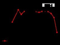
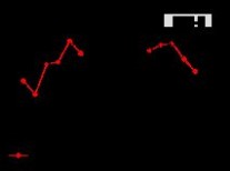
Fig. 10

扩展:outrigger / outrigger konotta / outrigger酒店


Strength degradation of specimens
mmm


扩展:outrigger / outrigger konotta / outrigger酒店


m


//
NN
kk
ll
KK
Fig. 11 Rigidity degradation of specimens
4.4 Energy dissipation
The energy dissipation capacity of the joints could be evaluated by the equivalent
damping coefficient (he) presented by Nie et al. (2008b). The calculated he for the cycle
Structures Congress 2013 Downloaded from ascelibrary.org by HUNAN UNIVERSITY on 10/10/13. Copyright ASCE. For personal use only; all rights res
k-style Experimental research on seismic performance of K-style steel outrigger truss to
Structures Congress 2013 ? ASCE 20132811
where the peak load appeared are listed in Table 2. It could be seen that he for the south
truss is slightly higher than those of the east truss for the same specimen. This is due to
the smaller initial imperfections of the south truss and thus plumper hysteretic response.
The total dissipated energy Etotal could also be used to describe the energy absorbing
capacity of the joints, which is obtained by accumulating the energy from each half
cycle. As shown in Fig. 12, for specimen OTJ-2, Etotal of the south truss is slightly
higher than that of the east truss; for specimen OTJ-1, Etotal of the south truss is
obviously higher than that of the east truss in the beginning and became lower finally. erved.
This contributes to the fact that after a severe buckling occurred, the displacement


扩展:outrigger / outrigger konotta / outrigger酒店

loading level was reduced for the south truss.
m
.


m.


NNk/k/
lla
tatoottEE
Fig. 12 Energy consumed versus number of half cycles
4.5 Analysis of strain and cracks
Fig. 13 presents the strain response on the encased steel plate. In the figure, strain
gauge 1 lies nearest to the joint where the height of steel plate is larger; Strain gauge 2
lies on the coupled beam where holes exist above and below; Strain gauge 3 lies furthest
from the joint. It can be seen that the steel plate is under compression with a positive
load and under tension with a negative load. The compressive strain is obviously
smaller than the tensile strain, which contributes to the fact that concrete has a good
compressive capacity and a poor tensile capacity. The strain gauge 2 exhibits a lager
strain than the other two gauges because of the larger height of steel plate for gauge 1
and larger distance from the joint for gauge 3.
Fig. 9(a) shows the cracking pattern of the wall for both specimens. The diagonal
cracks are caused because the wall is under shear due to the reverse tensile force and
compressive force of the upper and lower steel plate in the wall. The angles between the
扩展:outrigger / outrigger konotta / outrigger酒店
diagonal cracks and horizontal direction are a little larger than 45° due to the change of
the principle tensile stress direction of the concrete subjected to the axial load. It is thus
concluded that the concrete wall between the upper and lower steel plate acts like a
diagonal strut.
Structures Congress 2013 Downloaded from ascelibrary.org by HUNAN UNIVERSITY on 10/10/13. Copyright ASCE. For personal use only; all rights res
k-style Experimental research on seismic performance of K-style steel outrigger truss to


Structures Congress 2013 ? ASCE 20132812
erved.P/k


N
Fig. 13 Load-strain curves of encased steel plate (specimen OTJ-2)
4.6 Influence of different joint details
It was observed that the joint detail has a moderate effect on the P-Δ curve. The
stiffness and maximum load of specimen OTJ-1 are slightly higher than those of
specimen OTJ-2 while the displacement corresponding to the maximum load of
specimen OTJ-1 is obviously larger. The ductility coefficient μ and equivalent damping
扩展:outrigger / outrigger konotta / outrigger酒店
coefficient he for OTJ-1 are larger than those for OTJ-2. This is due to the fact that the
section of the truss members near the wall became narrow for specimen OTJ-2, then the
buckling capacity and stiffness were reduced and buckling occurred earlier. It could also
be seen that the cracking of the wall is more severe for specimen OTJ-2, such as the
spalling of large amount of concrete on the wall below the lower joint plate and
horizontal cracks on the wall where encased steel plate exists. This contributes to the
fact that the steel plate of specimen OTJ-1 is placed outside the wall and the cracks are
thus invisible. It could be observed from the reinforcement details and the preparation of
both specimens that OTJ-1 is much more convenient to construct than OTJ-2 since the
steel plate is outside the wall, the number of steel bars is thus reduced and concrete are
cast more easily.
5 CONCLUSIONS
The following conclusions can be drawn based on the experimental evaluations
within the limitations of the research presented in this paper:
(1). Generally, the failure mode of the joints is the elasto-plastic buckling of the
truss members. It was observed that the tested specimens behaved in a relatively ductile
manner. The experimental results presented in this paper show that these two joints
have a prospect to be applied in seismic region.
(2). It was found from the experimental results that the seismic performance of
specimen OTJ-1 with outside steel plate is better than those of specimen OTJ-2 with
Structures Congress 2013 Downloaded from ascelibrary.org by HUNAN UNIVERSITY on 10/10/13. Copyright ASCE. For personal use only; all rights res
k-style Experimental research on seismic performance of K-style steel outrigger truss to
Structures Congress 2013 ? ASCE 20132813
encased steel plate. The stiffness and maximum load of specimen OTJ-1 is slightly
larger than that of OTJ-2 while the displacement corresponding to the maximum load of
specimen OTJ-1 is obviously larger. It could also be seen that the cracking of the wall is
more severe for specimen OTJ-2.
(3). It could be observed from the reinforcement details and the preparation of both
erved.specimens that specimen OTJ-1 is much more convenient to construct than specimen OTJ-2 since the steel plate is outside the wall, the number of steel bars is thus reduced and concrete are cast more easily.
ACKNOWLEDGMENTS
The writers gratefully acknowledge the financial support provided by "Twelfth
Five-Year" plan major projects supported by National Science and Technology (Grant
No. 2011BAJ09B01) and Tsinghua University Initiative Scientific Research Program
(Grant No. 2010Z03078).
REFERENCES
Han, L.H., and Li, W. (2010). “Seismic performance of CFST column to steel beam joint with RC slab:
Experiments.” J. Constr. Steel Res., 66(11), 1374-1386.
Lei, Q., Liu, G.Y., and Hou, S.L. (2011). “Structural preliminary design of exceed-limit high-rise building
of Kingkey Financial Center.” Build. Struct., 41(S1), 346-351(in Chinese).
Ma, C.J., Zhang, L.P., and Fan, Z. (2009). “Nonlinear finite element analysis on connection joint of a
super high-rise building.” Build. Struct., 39(9), 60-62(in Chinese).
Nie, J.G., Qin, K., and Cai, C.S. (2008a). “Seismic behavior of connections composed of CFSSTCs and
steel-concrete composite beams-experimental study.” J. Constr. Steel Res., 64(10), 1178-1191.
Nie, J.G., Bai, Y., and Cai, C.S. (2008b). “New Connection System for Confined Concrete Columns and
Beams. I: Experimental Study.” ASCE J. Struct. Eng., 134(12), 1787-1799.
Park, R., Priestley, M.J., and Gill, W.D. (1982). “Ductility of square confined concrete columns.” ASCE J.
Struct. Div., 108(4), 929-950.
Park, W.S., and Yun, H.D. (2005). “Seismic behavior of coupling beams in a hybrid coupled shear walls.”
J. Constr. Steel Res., 61(11), 1492-1524.
Shahrooz, B.M. (1993). “Seismic design and performance of composite coupled walls.” ASCE J. Struct.
Eng., 119(11), 3291-3309.
Shahrooz, B.M., Deason, J.T., and Tunc, G. (2004a). “Outrigger beam-wall connections. I: Component
testing and development of design model.” ASCE J. Struct. Eng., 130(2), 253-261.
Shahrooz, B.M., Tunc, G., and Deason, J.T. (2004b). “Outrigger beam-wall connections. II: Subassembly
testing and further modeling enhancements.” ASCE J. Struct. Eng., 130(2), 262-270.
Wang, D.S., and Zhou, J.L. (2010). “Development and prospect of hybrid high-rise building structures in
China.” J. Build. Struct., 31(6), 62-70 (in Chinese).
Wu, J.R., and Li, Q.S. (2003). “Structural performance of multi-outrigger-braced tall buildings.” Struct.
Design Tall Spec. Build., 12(2), 155–176.
扩展:outrigger / outrigger konotta / outrigger酒店
Zhou, J., Chen, K., and Zhang, Y.F., et al. (2012). “Structural design on Wuhan Center Tower. Building
Structure.” Build. Struct., 42(5), 8-12(in Chinese).
Structures Congress 2013 Downloaded from ascelibrary.org by HUNAN UNIVERSITY on 10/10/13. Copyright ASCE. For personal use only; all rights res
扩展:outrigger / outrigger konotta / outrigger酒店
本文标题:on style-Experimental research on seismic performance of K-style s61阅读| 精彩专题| 最新文章| 热门文章| 苏ICP备13036349号-1