一 : booth算法超详细讲解
Booth Recoding
[Last modified 11:53:37 AM on Saturday, 8 May ]
Booth multiplication is a technique that allows for smaller, faster multiplication circuits, by recoding the numbers that are multiplied. It is the standard technique used in chip design, and provides significant improvements over the "long multiplication" technique.
Shift and Add
A standard approach that might be taken by a novice to perform multiplication is to "shift and add", or normal "long multiplication". That is, for each column in the multiplier, shift the multiplicand the appropriate number of columns and multiply it by the value of the digit in that column of the multiplier, to obtain a partial product. The partial products are then added to obtain the final result:.
0 0 1 0 1 1 0 1 0 0 1 1
0 0 1 0 1 1
0 0 1 0 1 1
0 0 0 0 0 0
0 0 0 0 0 0 0 0 1 0 1 1
0 0 1 1 0 1 0 0 0 1
With this system, the number of partial products is exactly the number of columns in the multiplier.
Reducing the Number of Partial Products
It is possible to reduce the number of partial products by half, by using the technique of radix 4 Booth recoding. The basic idea is that, instead of shifting and adding for every column of the multiplier term and multiplying by 1 or 0, we only take every second column, and multiply by ±1, ±2, or 0, to obtain the same results. So, to multiply by 7, we can multiply the partial product aligned against the least significant bit by -1, and multiply the partial product aligned with the third column by 2:
booth算法 booth算法超详细讲解
Partial Product 0 = Multiplicand * -1, shifted left 0 bits (x -1)
Partial Product 1 = Multiplicand * 2, shifted left 2 bits (x 8)
This is the same result as the equivalent shift and add method:
Partial Product 0 = Multiplicand * 1, shifted left 0 bits (x 1)
Partial Product 1 = Multiplicand * 1, shifted left 1 bits (x 2)
Partial Product 2 = Multiplicand * 1, shifted left 2 bits (x 4)
Partial Product 3 = Multiplicand * 0, shifted left 3 bits (x 0)
The advantage of this method is the halving of the number of partial products. This is important in circuit design as it relates to the propagation delay in the running of the circuit, and the complexity and power consumption of its implementation.
It is also important to note that there is comparatively little complexity penalty in multiplying by 0, 1 or 2. All that is needed is a multiplexer or equivalent, which has a delay time that is independent of the size of the inputs. Negating 2's complement numbers has the added complication of needing to add a "1" to the LSB, but this can be overcome by adding a single correction term with the necessary "1"s in the correct positions.
Radix-4 Booth Recoding
To Booth recode the multiplier term, we consider the bits in blocks of three, such that each block overlaps the previous block by one bit. Grouping starts from the LSB, and the first block only uses two bits of the multiplier (since there is no previous block to overlap):

Figure 1 : Grouping of bits from the multiplier term, for use in Booth recoding. The least significant
block uses only two bits of the multiplier, and assumes a zero for the third bit.
The overlap is necessary so that we know what happened in the last block, as the MSB of the
booth算法 booth算法超详细讲解
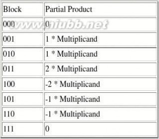
Table 1 : Booth recoding strategy for each of the possible block values.
Since we use the LSB of each block to know what the sign bit was in the previous block, and there are never any negative products before the least significant block, the LSB of the first block is always assumed to be 0. Hence, we would recode our example of 7 (binary 0111) as : 0 1 1 1
block 0 : 1 1 0 Encoding : * (-1)
block 1 : 0 1 1 Encoding : * (2)
In the case where there are not enough bits to obtain a MSB of the last block, as below, we sign extend the multiplier by one bit.
0 0 1 1 1
block 0 : 1 1 0 Encoding : * (-1)
block 1 : 0 1 1 Encoding : * (2)
block 2 : 0 0 0 Encoding : * (0)
The previous example can then be rewritten as:
0 0 1 0 1 1 , multiplicand
0 1 0 0 1 1 , multiplier
1 1 -1 , booth encoding of multiplier
1 1 1 1 1 1 0 1 0 0 , negative term sign extended
0 0 1 0 1 1
0 0 1 0 1 1
0 0 0 0 1 , error correction for negation 0 0 1 1 0 1 0 0 0 1 , discarding the carried high bit
booth算法 booth算法超详细讲解
One possible implementation is in the form of a Booth recoder entity, such as the one in figure 2-16, with its outputs being used to form the partial product:

Figure 2 : Booth Recoder and its associated inputs and outputs.
In figure 2,
?
?
? The zero signal indicates whether the multiplicand is zeroed before being used as a partial product The shift signal is used as the control to a 2:1 multiplexer, to select whether or not the partial product bits are shifted left one position. Finally, the neg signal indicates whether or not to invert all of the bits to create a negative product (which must be corrected by adding "1" at some later stage)
The described operations for booth recoding and partial product generation can be expressed in terms of logical operations if desired but, for synthesis, it was found to be better to implement the truth tables in terms of VHDL case and if/then/else statements.
Sign Extension Tricks
Once the Booth recoded partial products have been generated, they need to be shifted and added together in the following fashion:
[Partial Product 1]
[Partial Product 2] 0 0
[Partial Product 3] 0 0 0 0
[Partial Product 4] 0 0 0 0 0 0
The problem with implementing this in hardware is that the first partial product needs to be sign extended by 6 bits, the second by four bits, and so on. This is easily achievable in hardware, but requires additional logic gates than if those bits could be permanently kept constant. 1 1 1 1 1 1 1 0 1 0 0
0 0 0 0 0 1 0 1 1
booth算法 booth算法超详细讲解
0 0 0 1 0 1 1 0 0 0 0 1 , error correction for negation 0 0 1 1 0 1 0 0 0 1
Fortunately, there is a technique that achieves this:
?
?
? Invert the most significant bit (MSB) of each partial product Add an additional '1' to the MSB of the first partial product Add an additional '1' in front of each partial product
This technique allows any sign bits to be correctly propagated, without the need to sign extend all of the bits.
0 1 0 1 0 1 1 (additional "1"s)
0 0 1 0 0
1 1 0 1 1
1 1 0 1 1 0 0 0 0 1 , error correction for negation 0 0 1 1 0 1 0 0 0 1
References
? Weste, Neil H.E. and Eshraghian, Kamran, Principles of CMOS VLSI Design: A systems perspective, Addison-Wesley Publishing Company, 2nd ed., 1993, pp547-555.
二 : booth算法超详细讲解
Booth Recoding
[Last modified 11:53:37 AM on Saturday, 8 May ]
Booth multiplication is a technique that allows for smaller, faster multiplication circuits, by recoding the numbers that are multiplied. It is the standard technique used in chip design, and provides significant improvements over the "long multiplication" technique.
Shift and Add
A standard approach that might be taken by a novice to perform multiplication is to "shift and add", or normal "long multiplication". That is, for each column in the multiplier, shift the multiplicand the appropriate number of columns and multiply it by the value of the digit in that column of the multiplier, to obtain a partial product. The partial products are then added to obtain the final result:.
0 0 1 0 1 1 0 1 0 0 1 1
0 0 1 0 1 1
0 0 1 0 1 1
0 0 0 0 0 0
0 0 0 0 0 0 0 0 1 0 1 1
0 0 1 1 0 1 0 0 0 1
With this system, the number of partial products is exactly the number of columns in the multiplier.
Reducing the Number of Partial Products
It is possible to reduce the number of partial products by half, by using the technique of radix 4 Booth recoding. The basic idea is that, instead of shifting and adding for every column of the multiplier term and multiplying by 1 or 0, we only take every second column, and multiply by ±1, ±2, or 0, to obtain the same results. So, to multiply by 7, we can multiply the partial product aligned against the least significant bit by -1, and multiply the partial product aligned with the third column by 2:
Partial Product 0 = Multiplicand * -1, shifted left 0 bits (x -1)
Partial Product 1 = Multiplicand * 2, shifted left 2 bits (x 8)
This is the same result as the equivalent shift and add method:
Partial Product 0 = Multiplicand * 1, shifted left 0 bits (x 1)
Partial Product 1 = Multiplicand * 1, shifted left 1 bits (x 2)
Partial Product 2 = Multiplicand * 1, shifted left 2 bits (x 4)
Partial Product 3 = Multiplicand * 0, shifted left 3 bits (x 0)
The advantage of this method is the halving of the number of partial products. This is important in circuit design as it relates to the propagation delay in the running of the circuit, and the complexity and power consumption of its implementation.
It is also important to note that there is comparatively little complexity penalty in multiplying by 0, 1 or 2. All that is needed is a multiplexer or equivalent, which has a delay time that is independent of the size of the inputs. Negating 2's complement numbers has the added complication of needing to add a "1" to the LSB, but this can be overcome by adding a single correction term with the necessary "1"s in the correct positions.
Radix-4 Booth Recoding
To Booth recode the multiplier term, we consider the bits in blocks of three, such that each block overlaps the previous block by one bit. Grouping starts from the LSB, and the first block only uses two bits of the multiplier (since there is no previous block to overlap):

Figure 1 : Grouping of bits from the multiplier term, for use in Booth recoding. The least significant
block uses only two bits of the multiplier, and assumes a zero for the third bit.
The overlap is necessary so that we know what happened in the last block, as the MSB of the
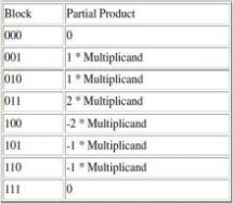
Table 1 : Booth recoding strategy for each of the possible block values.
Since we use the LSB of each block to know what the sign bit was in the previous block, and there are never any negative products before the least significant block, the LSB of the first block is always assumed to be 0. Hence, we would recode our example of 7 (binary 0111) as : 0 1 1 1
block 0 : 1 1 0 Encoding : * (-1)
block 1 : 0 1 1 Encoding : * (2)
In the case where there are not enough bits to obtain a MSB of the last block, as below, we sign extend the multiplier by one bit.
0 0 1 1 1
block 0 : 1 1 0 Encoding : * (-1)
block 1 : 0 1 1 Encoding : * (2)
block 2 : 0 0 0 Encoding : * (0)
The previous example can then be rewritten as:
0 0 1 0 1 1 , multiplicand
0 1 0 0 1 1 , multiplier
1 1 -1 , booth encoding of multiplier
1 1 1 1 1 1 0 1 0 0 , negative term sign extended
0 0 1 0 1 1
0 0 1 0 1 1
0 0 0 0 1 , error correction for negation 0 0 1 1 0 1 0 0 0 1 , discarding the carried high bit
One possible implementation is in the form of a Booth recoder entity, such as the one in figure 2-16, with its outputs being used to form the partial product:

Figure 2 : Booth Recoder and its associated inputs and outputs.
In figure 2,
?
?
? The zero signal indicates whether the multiplicand is zeroed before being used as a partial product The shift signal is used as the control to a 2:1 multiplexer, to select whether or not the partial product bits are shifted left one position. Finally, the neg signal indicates whether or not to invert all of the bits to create a negative product (which must be corrected by adding "1" at some later stage)
The described operations for booth recoding and partial product generation can be expressed in terms of logical operations if desired but, for synthesis, it was found to be better to implement the truth tables in terms of VHDL case and if/then/else statements.
Sign Extension Tricks
Once the Booth recoded partial products have been generated, they need to be shifted and added together in the following fashion:
[Partial Product 1]
[Partial Product 2] 0 0
[Partial Product 3] 0 0 0 0
[Partial Product 4] 0 0 0 0 0 0
The problem with implementing this in hardware is that the first partial product needs to be sign extended by 6 bits, the second by four bits, and so on. This is easily achievable in hardware, but requires additional logic gates than if those bits could be permanently kept constant. 1 1 1 1 1 1 1 0 1 0 0
0 0 0 0 0 1 0 1 1
0 0 0 1 0 1 1 0 0 0 0 1 , error correction for negation 0 0 1 1 0 1 0 0 0 1
Fortunately, there is a technique that achieves this:
?
?
? Invert the most significant bit (MSB) of each partial product Add an additional '1' to the MSB of the first partial product Add an additional '1' in front of each partial product
This technique allows any sign bits to be correctly propagated, without the need to sign extend all of the bits.
0 1 0 1 0 1 1 (additional "1"s)
0 0 1 0 0
1 1 0 1 1
1 1 0 1 1 0 0 0 0 1 , error correction for negation 0 0 1 1 0 1 0 0 0 1
References
? Weste, Neil H.E. and Eshraghian, Kamran, Principles of CMOS VLSI Design: A systems perspective, Addison-Wesley Publishing Company, 2nd ed., 1993, pp547-555.
本文标题:booth算法详解-booth算法超详细讲解61阅读| 精彩专题| 最新文章| 热门文章| 苏ICP备13036349号-1