一 : NeotecWELLFLOV8.1.6
下图为Neotec WELLFLO V8.1.6版
联系邮箱:zhongtiany01@163.com

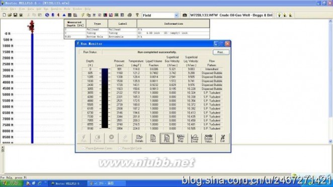
油气井生产、欠平衡钻井/控压钻井水力学模拟软件WELLFLO软件是SPTGroup—Neotec公司经过36年研发和实践编制出的油气井生产、欠平衡钻井/控压钻井水力学模拟软件。用来模拟生产井或注入井的水力学和传热过程,WELLFLO提供三个用户界面包括WELLFLOExpert、WELLFLO Rigsite、WELLFLO Production.
WELLFLO可用于模拟人工举升,多层开采、欠平衡钻井、油套管合采以及井筒加热注蒸汽等工艺过程;能准确计算井筒多相流压力温度变化,尤其对凝析气/高酸性气体更准确,能够预测和预防井筒积液,优化井的生产制度;WELLFLO能够对稠油井采油工艺进行评估,模拟复杂流体流动,优化环空设计,预测水合物生成。动态和静态两种模式的结合满足了快速设计和详细分析两方面的需要,这样使用户可以获得最优方案。
| WELLFLO软件功能 · 人工举升(气举,ESP) · 多层合采 · 油套管合采 · 隔热油管 · 环空电加热 · 井筒加热 · 注蒸汽 · 井稳定性分析 | 欠平衡钻井/压力控制钻井中的应用 · 优化注入压力和注入量 · 评估UBD需要的钻井液 · 监控钻井过程 |
二 : 欢度6.1
六一儿童节是儿童的盛宴。在儿童节里,我们欢庆着属于自己的时光。今天是一年一度的六一儿童节,每一位同学的脸上都挂着欣喜、快乐的笑容。我们来到学校的大礼堂,准备参加六一儿童节歌咏大赛,和其他班的同学来个PK比赛!都说儿童的歌声是天籁之音。果不其然,每个班都唱得那么好。我最喜欢的就数六(1)班的《虫儿飞》了。同学们站在舞台上,缓缓的抒情音乐响起,大家轻轻唱了起来:“黑黑的天空低垂,亮亮的繁星相随……”我们好像真的到了一个仙境般的地方,到处都是闪着微弱的光芒的萤火虫,萦绕在我们的身边。夜空上的繁星一闪一闪,微风吹拂着我们,好似在诉说一个美丽的故事。萤火虫飞啊飞啊,跳着美丽的舞蹈,在我们身边旋转、舞蹈……一曲终了,我们才清醒过来,意犹未尽,还想再听一遍。终于轮到我们上场了!我们走上台,微笑着面对观众。音乐响起,清脆的歌声也随之响起,流淌在同学们之间。第一首是《让我们荡起双桨》。唱着,唱着,大家好像真的坐在小船里,一边划船一边唱歌。小船儿漂啊漂,伴着同学们一起歌唱,直到音乐结束。大家还没缓过神来呢,轻快、活泼的乐曲就又响了起来。哦!《蜗牛与黄鹂鸟》已经开始了。我们立刻换上了一副高兴的笑容,倾情演唱这首歌。大家好像也被我们感染了一样,俏皮的笑容展开在脸上。活动在同学们的歌声、笑声中结束了。虽然比赛我们只得了第三名,但是名次不是重要的,只要开心就好了,不是吗?
树人六年级:王鑫
三 : Eurocode3-1-6
CEN/TC250/SC3/
EUROPEAN STANDARD prEN 1993-1-6 : 2004 NORME EUROPéENNE
EUROP?ISCHE NORM Oct 2004
___________________________________
UDC
Descriptors:
English version
Eurocode 3: Design of steel structures
Part 1-6 : Strength and Stability of Shell Structures
Calcul des structures en acier
Partie 1.6 :
Resistance et Stabilité des Coques
Bemessung und Konstruktion von Stahlbauten Teil 1.6 : Aus Schalen
Stage 49 ? draft
5 October 2004
CEN
European Committee for Standardisation Comité Européen de Normalisation Europ?isches Komitee für Normung
Central Secretariat: rue de Stassart 36, B-1050 Brussels
_______________________________
Ref. No. EN 1993-1.6 : 20xx. E
? CEN Copyright reserved to all CEN members
tiffen Eurocode3-1-6
Page 2
EN 1993-1-6: 20xx Contents Page
1. Introduction
1.1 Scope 1.2 Normative references 1.3 Definitions 1.4 Symbols 1.5 Sign conventions 2
Basis of design and modelling 2.1 General 2.2 Types of analysis
2.3 Shell boundary conditions 3 Materials and geometry
3.1 Material properties
3.2 Design values of geometrical data
3.3 Geometrical tolerances and geometrical imperfections 4
Ultimate limit states in steel shells 4.1 Ultimate limit states to be considered
4.2 Design concepts for the limit states design of shells
5
Stress resultants and stresses in shells 5.1 Stress resultants in the shell
5.2 Modelling of the shell for analysis 5.3 Types of analysis
6 Plastic limit state (LS1)
6.1 Design values of actions 6.2 Stress design
6.3 Design by global numerical MNA or GMNA analysis 6.4 Direct design
7 Cyclic plasticity limit state (LS2)
7.1 Design values of actions 7.2 Stress design
7.3 Design by global numerical MNA or GMNA analysis 7.4 Direct design
8 Buckling limit state (LS3)
8.1 Design values of actions
8.2 Special definitions and symbols
8.3 Buckling-relevant boundary conditions 8.4 Buckling-relevant geometrical tolerances 8.5 Stress design
8.6 Design by global numerical analysis using MNA and LBA analyses 8.7 Design by global numerical GMNIA analysis
9 Fatigue limit state (LS4)
9.1 Design values of actions 9.2 Stress design
9.3 Design by global numerical LA or GNA analysis
5 5 6 6 10 13 14 14 14 16 17 17 17 17 18 18 19 22 22 22 24 25 25 25 26 26 28 28 28 28 29 30 30 30 30 30 36 38 40 45 45 45 46
tiffen Eurocode3-1-6
ANNEX A (normative)
Membrane theory stresses in shells
A.1 General
A.2 Unstiffened Cylindrical Shells A.3 Unstiffened Conical Shells A.4 Unstiffened Spherical Shells ANNEX B (normative)
Additional expressions for plastic collapse resistances
B.1 General B.2 Unstiffened cylindrical shells B.3 Ring stiffened cylindrical shells B.4 Junctions between shells
B.5 Circular plates with axisymmetric boundary conditions ANNEX C (normative)
Expressions for linear elastic membrane and bending stresses
C.1 General
C.2 Clamped base unstiffened cylindrical shells C.3 Pinned base unstiffened cylindrical shells
C.4 Internal conditions in unstiffened cylindrical shells C.5 Ring stiffener on cylindrical shell
C.6 Circular plates with axisymmetric boundary conditions ANNEX D [normative]
Expressions for buckling stress design
D.1 Unstiffened cylindrical shells of constant wall thickness
D.2 Unstiffened cylindrical shells of stepwise variable wall thickness D.3 Unstiffened lap jointed cylindrical shells
D.4 Unstiffened complete and truncated conical shells
Page 3
EN 1993-1-6: 20xx
47 47 47 48 49 50 51 51 51 52 54 56 58 59 59 59 60 62 64 66 67 69 69 69 78 82 84
tiffen Eurocode3-1-6
Page 4
EN 1993-1-6: 20xx
National annex for EN 1993-1-6
This standard gives alternative procedures, values and recommendations with notes indicating where national choices may have to be made. Therefore the National Standard implementing EN 1993-1-6 should have a National Annex containing all Nationally Determined Parameters to be used for the design of steel structures to be constructed in the relevant country.
National choice is allowed in EN 1993-1-6 through:
?
?
? 4.1.4 (3) 5.2.4 (1) 6.3 (5)
? 7.3.1 (5)
? 7.3.2 (1)
?
?
? 8.4.2 Table 8.1 8.4.3 Tables 8.2 and 8.3 8.4.4 Table 8.4
? 8.4.5 (1)
? 8.5.2 (2)
?
?
8.7.2 Table 8.5 8.7.2 (7), (16) and (18) ? 9.2.1 (2)
tiffen Eurocode3-1-6
Page 5
EN 1993-1-6: 20xx
1. Introduction
1.1 Scope
(1) EN 1993-1-6 gives design requirements for plated steel structures that have the form of a shell of revolution.
(2) This Standard is intended for use in conjunction with EN 1993-1-1, EN 1993-1-3, EN 1993-1-4, EN 1993-1-9 and the relevant application parts of EN 1993, which include:
扩展:eurocode3 中文版 / eurocode 3 / eurocode3 中文
? Part 3.1 for towers and masts;
? Part 3.2 for chimneys;
? Part 4.1 for silos;
? Part 4.2 for tanks;
? Part 4.3 for pipelines.
(3) This Standard defines the characteristic and design values of the resistance of the structure.
(4) This Standard is concerned with the requirements for design against the ultimate limit states of: ? plastic limit;
? cyclic plasticity;
? buckling;
? fatigue.
(5) Overall equilibrium of the structure (sliding, uplifting, overturning) is not included in this Standard, but is treated in EN 1993-1-1. Special considerations for specific applications are included in the relevant applications parts of EN 1993.
(6) The provisions in this Standard apply to axisymmetric shells and associated circular or annular plates and to beam section rings and stringer stiffeners where they form part of the complete structure. The following shell forms are covered: cylinders, cones and spherical caps.
(7) Cylindrical, conical and spherical panels are not explicitly covered by this Standard. However, the provisions can be applicable if the appropriate boundary conditions are duly taken into account.
(8) This Standard is intended for application to structural engineering steel shell structures. However, its provisions can be applied to other metallic shells provided that the appropriate material properties are duly taken into account.
(9) The provisions of this Standard are intended to be applied within the temperature range defined in the relevant EN 1993 application parts. The maximum temperature is restricted so that the influence of creep can be neglected if high temperature creep effects are not covered by the relevant application part.
(10) The provisions in this Standard apply to structures that satisfy the brittle fracture provisions given in EN 1993-1-10.
(11) The provisions of this Standard apply to structural design under actions that can be treated as quasi-static in nature.
(12) In this Standard, it is assumed that both wind loading and bulk solids flow can, in general, be treated as quasi-static actions.
(13) Dynamic effects should be taken into account according to the relevant application part of EN 1993, including the consequences for fatigue. However, the stress resultants arising from dynamic behaviour are treated in this part as quasi-static.
(14) The provisions in this Standard apply to structures that are constructed in accordance with EN 1090.
(15) This Standard does not cover the aspects of leakage of contents.
tiffen Eurocode3-1-6
Page 6
EN 1993-1-6: 20xx
(16) This Standard is not intended for application to structures outside the following limits:
? design metal temperatures outside the range ?50°C to +300°C;
? radius to thickness ratios outside the range 20 to 5000.
NOTE: It should be noted that the hand calculation rules of this standard may be rather conservative when applied to some geometries and loading conditions for relatively thick-walled shells.
1.2 Normative references
(1) This European Standard incorporates, by dated or undated reference, provisions from other publications. These normative references are cited at the appropriate places in the text and the publications are listed hereafter. For dated references, subsequent amendments to or revisions of any of these publications apply to this European Standard only when incorporated in it by amendment or revision. For undated references the latest edition of the publication referred to applies.
EN 1090
EN 1990
EN 1991 EN 1993
Part 1.1:
Part 1.3:
Part 1.4:
Part 1.5:
Part 1.9:
Part 1.10:
Part 2:
Part 3.1:
Part 3.2:
Part 4.1:
Part 4.2:
Part 4.3:
EN 13084
Part 7:
Execution of steel structures: Basis of design; Eurocode 3: Design of steel structures: General rules and rules for buildings; Cold formed members and sheeting; Stainless steels; Plated structural elements; Fatigue; Material toughness and through-thickness properties; Steel bridges; Towers and masts; Chimneys; Silos; Tanks; Pipelines. Free standing chimneys: Product specification of cylindrical steel fabrications for use in single wall steel chimneys and steel liners.
1.3 Definitions
The terms that are defined in EN 1990 for common use in the Structural Eurocodes apply to this Standard. Unless otherwise stated, the definitions given in ISO 8930 also apply in this Standard. Supplementary to EN 1993-1-1, for the purposes of this Standard, the following definitions apply:
1.3.1 Structural forms and geometry
1.3.1.1
shell
A structure or a structural component formed from a curved thin plate.
tiffen Eurocode3-1-6
Page 7
EN 1993-1-6: 20xx
1.3.1.2
shell of revolution
扩展:eurocode3 中文版 / eurocode 3 / eurocode3 中文
A shell whose form is defined by a meridional generator line rotated around a single axis through 2π radians. The shell can be of any length.
1.3.1.3
complete axisymmetric shell
A shell composed of a number of parts, each of which is a shell of revolution.
1.3.1.4
shell segment
A shell of revolution in the form of a defined shell geometry with a constant wall thickness: a cylinder, conical frustum, spherical frustum, annular plate, toroidal knuckle or other form.
1.3.1.5
shell panel
An incomplete shell of revolution: the shell form is defined by a rotation of the generator about the axis through less than 2π radians.
1.3.1.6
middle surface
The surface that lies midway between the inside and outside surfaces of the shell at every point. Where the shell is stiffened on only one surface, the reference middle surface is still taken as the middle surface of the curved shell plate. The middle surface is the reference surface for analysis, and can be discontinuous at changes of thickness or shell junctions, leading to eccentricities that may be important to the shell structural behaviour.
1.3.1.7
junction
The point at which two or more shell segments meet: it can include a stiffener or not: the point of attachment of a ring stiffener to the shell may be treated as a junction.
1.3.1.8
stringer stiffener
A local stiffening member that follows the meridian of the shell, representing a generator of the shell of revolution. It is provided to increase the stability, or to assist with the introduction of local loads. It is not intended to provide a primary resistance to bending effects caused by transverse loads.
1.3.1.9
rib
A local member that provides a primary load carrying path for bending down the meridian of the shell, representing a generator of the shell of revolution. It is used to transfer or distribute transverse loads by bending.
1.3.1.10
ring stiffener
A local stiffening member that passes around the circumference of the shell of revolution at a given point on the meridian. It is assumed to have no stiffness in the meridional plane of the shell. It is provided to increase the stability or to introduce axisymmetric local loads acting in the plane of the ring by a state of axisymmetric normal forces. It is not intended to provide primary resistance for bending.
1.3.1.11
base ring
A structural member that passes around the circumference of the shell of revolution at the base and provides means of attachment of the shell to a foundation or other structural member. It is needed to ensure that the assumed boundary conditions are achieved in practice.
1.3.1.12
ring beam or ring girder
A circumferential stiffener that has bending stiffness and strength both in the plane of the shell circular section and normal to that plane. It is a primary load carrying structural member, provided for the distribution of local loads into the shell.
tiffen Eurocode3-1-6
Page 8
EN 1993-1-6: 20xx
1.3.2 Limit states
1.3.2.1
plastic limit
The ultimate limit state where the structure develops zones of yielding in a pattern such that its ability to resist increased loading is deemed to be exhausted. It can be related to a small deflection theory limit load or plastic collapse mechanism.
1.3.2.2
tensile rupture
The ultimate limit state where the shell plate experiences gross section failure due to tension.
1.3.2.3
cyclic plasticity
The ultimate limit state where repeated yielding is caused by cycles of loading and unloading, leading to a low cycle fatigue failure where the energy absorption capacity of the material is exhausted.
1.3.2.4
buckling
The ultimate limit state where the structure suddenly loses its stability under membrane compression and/or shear. It leads either to large displacements or to the structure being unable to support the applied loads.
1.3.2.5
fatigue
The ultimate limit state where many cycles of loading cause cracks to develop of the shell plate.
1.3.3 Actions
1.3.3.1
axial load
Externally applied loading acting in the axial direction.
1.3.3.2
radial load
Externally applied loading acting normal to the surface of a cylindrical shell.
1.3.3.3
internal pressure
Component of the surface loading acting axisymmetrically, normal to the shell in the outward direction. Its magnitude can vary in both the meridional and circumferential directions (e.g. under solids loading in a silo).
1.3.3.4
external pressure
Component of the surface loading acting axisymmetrically, normal to the shell in the inward direction. It magnitude can vary in both the meridional and circumferential directions (e.g. under wind).
1.3.3.5
hydrostatic pressure
扩展:eurocode3 中文版 / eurocode 3 / eurocode3 中文
Pressure varying linearly with the axial coordinate of the shell of revolution.
1.3.3.6
wall friction load
Meridional component of the surface loading acting along the wall due to friction connected with internal pressure (when solids are contained within the shell).
1.3.3.7
local load
Point applied force or distributed load acting on a limited part of the circumference of the shell and over a limited height.
1.3.3.8
patch load
Local distributed load acting normal to the shell.
tiffen Eurocode3-1-6
Page 9
EN 1993-1-6: 20xx
1.3.3.9
suction
Constant external pressure due to the sucking effect of the wind action on a shell with openings or vents.
1.3.3.10
partial vacuum
Constant external pressure due to the removal of stored liquids or solids from within a container with inadequate venting.
1.3.3.11
thermal action
Temperature variation either along or around the shell or through the shell thickness.
1.3.4 Types of analysis
1.3.4.1
global analysis
An analysis that includes the complete structure, rather than individual structural parts treated separately.
1.3.4.2
membrane theory analysis
An analysis that predicts the behaviour of a thin-walled shell structure under distributed loads by adopting a set of membrane forces that satisfy equilibrium with the external loads.
1.3.4.3
linear elastic shell analysis (LA)
An analysis that predicts the behaviour of a thin-walled shell structure on the basis of the small deflection linear elastic shell bending theory, related to the perfect geometry of the middle surface of the shell.
1.3.4.4
linear elastic bifurcation (eigenvalue) analysis (LBA)
An analysis that evaluates the linear bifurcation eigenvalue for a thin-walled shell structure on the basis of the small deflection linear elastic shell bending theory, related to the perfect geometry of the middle surface of the shell. It should be noted that, where an eigenvalue is mentioned, this does not relate to vibration modes.
1.3.4.5
geometrically nonlinear elastic analysis (GNA)
An analysis based on the principles of shell bending theory applied to the perfect structure, using a linear elastic material law but including nonlinear, large deflection theory for the displacements. A bifurcation eigenvalue check is included at each load level.
1.3.4.6
materially nonlinear analysis (MNA)
An analysis based on shell bending theory applied to the perfect structure, using the assumption of small deflections, as in 1.3.4.3, but adopting a nonlinear elasto-plastic material law.
1.3.4.7
geometrically and materially nonlinear analysis (GMNA)
An analysis based on shell bending theory applied to the perfect structure, using the assumptions of nonlinear, large deflection theory for the displacements and a nonlinear, elasto-plastic material law. A bifurcation eigenvalue check is included at each load level.
1.3.4.8
geometrically nonlinear elastic analysis with imperfections included (GNIA)
An analysis with imperfections included, similar to a GNA analysis as defined in 1.3.4.5, but adopting a model for the geometry of the structure that includes the imperfect shape (i.e. the geometry of the middle surface includes unintended deviations from the ideal shape). A bifurcation eigenvalue check is included at each load level.
tiffen Eurocode3-1-6
Page 10
EN 1993-1-6: 20xx
1.3.4.9
geometrically and materially nonlinear analysis with imperfections included (GMNIA)
An analysis with imperfections included, similar to the GMNA analysis as defined in 1.3.4.7, but adopting a model for the geometry of the structure that includes the imperfect shape (i.e. the geometry of the middle surface includes unintended deviations from the ideal shape). A bifurcation eigenvalue check is included at each load level.
1.3.5 Special definitions for buckling calculations
1.3.5.1
critical buckling resistance
The smallest bifurcation or limit load determined assuming the idealised conditions of elastic material behaviour, perfect geometry, perfect load application, perfect support, material isotropy and absence of residual stresses (LBA analysis).
1.3.5.2
critical buckling stress
The nominal membrane stress (based on membrane theory) associated with the elastic critical buckling resistance.
1.3.5.3
characteristic buckling stress
The nominal membrane stress associated with buckling in the presence of inelastic material behaviour, the geometrical and structural imperfections that are inevitable in practical construction, and follower load effects.
1.3.5.4
design buckling stress
The design value of the buckling stress, obtained by dividing the characteristic buckling stress by the partial factor for resistance.
扩展:eurocode3 中文版 / eurocode 3 / eurocode3 中文
1.3.5.5
key value of the stress
The value of stress in a non-uniform stress field that is used to characterise the stress magnitudes in an LS3 assessment.
1.3.5.6
fabrication tolerance quality class
The category of fabrication tolerance requirements that is assumed in design.
1.4 Symbols
(1)
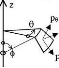
(2) In addition to those given in EN 1990 and EN 1993-1-1, the following symbols are used: Coordinate system (see figure 1.1):
r radial coordinate, normal to the axis of revolution;
x meridional coordinate;
z axial coordinate;
θ circumferential coordinate;
φ meridional slope: angle between axis of revolution and normal to the meridian of the shell;
(3) Pressures:
pn normal to the shell;
meridional surface loading parallel to the shell; px
circumferential surface loading parallel to the shell; pθ
(4) Line forces:
Pn load per unit circumference normal to the shell;
load per unit circumference acting in the meridional direction; Px
Pθ load per unit circumference acting circumferentially on the shell;
tiffen Eurocode3-1-6
Page 11
EN 1993-1-6: 20xx
(5) Membrane stress resultants:
nx meridional membrane stress resultant;
circumferential membrane stress resultant; nθ
membrane shear stress resultant; nxθ
Bending stress resultants:
mx meridional bending moment per unit width;
circumferential bending moment per unit width; mθ
twisting shear moment per unit width; mxθ
transverse shear force associated with meridional bending; qxn
transverse shear force associated with circumferential bending; qθn (6)
(7) Stresses:
σx meridional stress;
stress; σθ circumferential
von Mises equivalent stress (can be negative in cyclic loading conditions); σeq
τ, τxθ in-plane shear stress;
τxn, τθn meridional, circumferential transverse shear stresses associated with bending;
(8) Displacements:
u meridional displacement;
v circumferential displacement;
w displacement normal to the shell surface;
βφ meridional rotation (see 5.2.2);
(9) Shell dimensions:
d internal diameter of shell;
L total length of the shell;
? length of shell segment;
?g gauge length for measurement of imperfections;
gauge length for measurement of imperfections in circumferential direction; ?gθ
gauge length for measurement of imperfections across welds; ?gw
limited length of shell for buckling strength assessment; ?R
r radius of the middle surface, normal to the axis of revolution; t thickness of shell wall;
maximum thickness of shell wall at a joint; tmax
minimum thickness of shell wall at a joint; tmin
tave average thickness of shell wall at a joint;
β apex half angle of cone;
tiffen Eurocode3-1-6
Page 12
EN 1993-1-6: 20xx
n

x
θ


vDisplacements
σx
x
Directions
Membrane stresses
ττθTransverse shear
stresses
Figure 1.1: Symbols in shells of revolution
(10) Tolerances (see 8.4):
e eccentricity between the middle surfaces of joined plates; Ue accidental eccentricity tolerance parameter;
out-of-roundness tolerance parameter; Ur
initial dimple imperfection amplitude parameter for numerical calculations; Un
initial dimple tolerance parameter; U0
tolerance normal to the shell surface; ?w0
(11) Properties of materials:
E Young’s modulus of elasticity; feq von Mises equivalent strength;
yield strength; fy
ultimate strength; fu
ν Poisson’s ratio;
(12) Parameters in strength assessment:
C coefficient in buckling strength assessment; D cumulative damage in fatigue assessment; F generalised action; R calculated resistance (used with subscripts to identify the basis);
plastic reference resistance (defined as a load factor on design loads); Rpl
elastic critical buckling resistance (defined as a load factor on design loads); Rcr
k calibration factor for nonlinear analyses; k power of interaction expressions in buckling strength interaction expressions; n number of cycles of loading; α elastic imperfection reduction factor in buckling strength assessment; β plastic range factor in buckling interaction; γ partial factor; ? range of parameter when alternating or cyclic actions are involved;
扩展:eurocode3 中文版 / eurocode 3 / eurocode3 中文
strain; εp plastic
η interaction exponent for buckling; ?λ relative slenderness of shell; ?overall relative slenderness for the complete shell (multiple segments); λov

tiffen Eurocode3-1-6
Page 13
EN 1993-1-6: 20xx
?λ0 ?λ
ω
χ
χov psquash limit relative slenderness (value of ?λ at which stability reductions commence); ?plastic limit relative slenderness (value of λ below which plasticity affects the stability); relative length parameter for shell; buckling reduction factor for elastic-plastic effects in buckling strength assessment; overall buckling resistance reduction factor for complete shell;
(13) Subscripts:
E value of stress or displacement (arising from design actions);
F actions;
M material;
R resistance;
S value of stress resultant (arising from design actions);
cr critical buckling value;
d design value;
int internal;
k characteristic value;
max maximum value;
min minimum value;
nom nominal value;
pl plastic value;
u ultimate;
y yield.
(14) Further symbols are defined where they first occur.
1.5 Sign conventions
(1) Outward direction positive: internal pressure positive, outward displacement positive, except as noted in (4).
(2) Tensile stresses positive, except as noted in (4).
NOTE: Compression is treated as positive in EN 1993-1-1.
(3) Shear stresses positive as shown in figures 1.1 and D.1.
(4) For simplicity, in section 8 and Annex D, compressive stresses are treated as positive. For these cases, both external pressures and internal pressures are treated as positive where they occur.
tiffen Eurocode3-1-6
Page 14
EN 1993-1-6: 20xx
2 Basis of design and modelling
2.1 General
(1) The basis of design shall be in accordance with EN 1990, as supplemented by the following.
(2) In particular, the shell shall be designed in such a way that it will sustain all actions and satisfy the following requirements:
? overall equilibrium;
? equilibrium between actions and internal forces and moments (see sections 6 and 8);
? limitation of cracks due to cyclic plastification (see section 7);
? limitation of cracks due to fatigue (see section 9).
(3) The design of the shell shall satisfy the serviceability requirements set out in the appropriate application standard (EN 1993 Parts 3.1, 3.2, 4.1, 4.2, 4.3).
(4) The shell may be proportioned using design assisted by testing. Where appropriate, the requirements are set out in the appropriate application standard (EN 1993 Parts 3.1, 3.2, 4.1, 4.2, 4.3).
(5) All actions should be introduced using their design values according to EN 1991 and EN 1993 Parts 3.1,
3.2, 4.1, 4.2, 4.3 as appropriate.
2.2 Types of analysis
2.2.1 General
(1) One or more of the following types of analysis should be used as detailed in section 4, depending on the limit state and other considerations:
? Global analysis (see 2.2.2);
? Membrane theory analysis (see 2.2.3);
? Linear elastic shell analysis (see 2.2.4);
? Linear elastic bifurcation analysis (see 2.2.5);
? Geometrically nonlinear elastic analysis (see 2.2.6);
? Materially nonlinear analysis (see 2.2.7);
? Geometrically and materially nonlinear analysis (see 2.2.8);
? Geometrically nonlinear elastic analysis with imperfections included (see 2.2.9);
? Geometrically and materially nonlinear analysis with imperfections included (see 2.2.10).
2.2.2 Global analysis
(1) A global analysis may involve approximate treatments of certain parts of the structure.
2.2.3 Membrane theory analysis
(1) A membrane theory analysis should not be used unless the following conditions are met:
? the boundary conditions are appropriate for transfer of the stresses in the shell into support reactions without causing bending effects;
? the shell geometry varies smoothly in shape (without discontinuities);
? the loads have a smooth distribution (without locally concentrated or point loads).
(2) A membrane theory analysis does not necessarily fulfil the compatibility of deformations at boundaries or between shell segments of different shape or between shell segments subjected to different loading. However, the resulting field of membrane forces satisfies the requirements of primary stresses (LS1).
2.2.4 Linear elastic shell analysis (LA)
(1) The linearity of the theory results from the assumptions of a linear elastic material law and the linear small deflection theory. Small deflection theory implies that the assumed geometry remains that of the undeformed structure.
(2) An LA analysis satisfies compatibility in the deformations as well as equilibrium. The resulting field of membrane and bending stress matches the requirements of primary plus secondary stresses (LS2).
扩展:eurocode3 中文版 / eurocode 3 / eurocode3 中文
tiffen Eurocode3-1-6
Page 15
EN 1993-1-6: 20xx
2.2.5 Linear elastic bifurcation analysis (LBA)
(1) The conditions of 2.2.4 concerning the material and geometric assumptions are met. However, this linear bifurcation analysis obtains the lowest eigenvalue at which the shell may buckle into a different deformation mode, assuming no change of geometry, no change in the direction of action of the loads, and no material degradation. Imperfections of all kinds are ignored. This analysis provides the basis of the critical buckling resistance evaluation (LS3).
2.2.6 Geometrically nonlinear elastic analysis (GNA)
(1) A GNA analysis satisfies both equilibrium and compatibility of the deflections under conditions in which the change in the geometry of the structure caused by loading is included. The resulting field of stresses matches the definition of primary plus secondary stresses (LS2).
(2) Where compression or shear stresses are predominant in some part of the shell, a GNA analysis delivers the elastic buckling load of the perfect structure, including changes in geometry, that may be of assistance in checking the limit state LS3 (see 8.7).
(3) Where this analysis is used for a buckling load evaluation, the eigenvalues of the system must be checked to ensure that the numerical process does not fail to detect a bifurcation in the load path.
2.2.7 Materially nonlinear analysis (MNA)
(1) The result of an MNA analysis gives the plastic limit load, which can be interpreted as a load amplification factor R on the design value of the loads FEd. This may be used to verify limit state LS1. An MNA analysis can also be used to give the plastic strain increment ?ε during one cycle of cyclic loading. This may be used to verify limit state LS2.
2.2.8 Geometrically and materially nonlinear analysis (GMNA)
(1) The result of a GMNA analysis, analogously to 2.2.5, gives the geometrically nonlinear plastic limit load of the perfect structure and the plastic strain increment, that may be used for checking the limit states LS1 and LS2.
(2) Where compression or shear stresses are predominant in some part of the shell, a GMNA analysis gives the elasto-plastic buckling load of the perfect structure, that may be of assistance in checking the limit state LS3 (see 8.7).
(3) Where this analysis is used for a buckling load evaluation, the eigenvalues of the system must be checked to ensure that the numerical process does not fail to detect a bifurcation in the load path.
2.2.9 Geometrically nonlinear elastic analysis with imperfections included (GNIA)
(1) A GNIA analysis is used in cases where compression or shear stresses dominate in the shell. It delivers elastic buckling loads of the "real" imperfect structure, that may be of assistance in checking the limit state LS3 (see 8.7).
(2) Where this analysis is used for a buckling load evaluation, the eigenvalues of the system must be checked to ensure that the numerical process does not fail to detect a bifurcation in the load path.
2.2.10 Geometrically and materially nonlinear analysis with imperfections included (GMNIA)
(1) A GMNIA analysis is used in cases where compression or shear stresses are dominant in the shell. It delivers elasto-plastic buckling loads for the "real" imperfect structure, that may be used for checking the limit state LS3.
(2) Where this analysis is used for a buckling load evaluation, the eigenvalues of the system must be checked to ensure that the numerical process does not fail to detect a bifurcation in the load path.
(3) Where this analysis is used for a buckling load evaluation, an additional GMNA analysis of the perfect shell should always be conducted to ensure that the degree of imperfection sensitivity of the structural system is identified.
tiffen Eurocode3-1-6
Page 16
EN 1993-1-6: 20xx
2.3 Shell boundary conditions
(1) The boundary conditions assumed in the design calculation shall be chosen in such a way as to ensure that they achieve a realistic or conservative model of the real construction. Special attention shall be given not only to the constraint of displacements normal to the shell wall (deflections), but also to the constraint of the displacements in the plane of the shell wall (meridional and circumferential) because of the significant effect these have on shell strength and buckling resistance.
(2) In shell buckling (eigenvalue) calculations (limit state LS3), the definition of the boundary conditions shall refer to the incremental displacements during the buckling process, and not to total displacements induced by the applied actions before buckling.
(3) The boundary conditions at a continuously supported lower edge of a shell shall take into account whether local uplifting of the shell is prevented or not.
(4) The shell edge rotation βφ should be particularly considered in short shells and in the calculation of secondary stresses in longer shells (according to the limit states LS2 and LS4).
扩展:eurocode3 中文版 / eurocode 3 / eurocode3 中文
(5) The boundary conditions set out in 5.2.2 should be used in computer analyses and in selecting expressions from Annexes A to D.
(6) The structural connections between shell segments at a junction should be such as to ensure that the boundary condition assumptions used in the design of the individual shell segments are satisfied.
tiffen Eurocode3-1-6
Page 17
EN 1993-1-6: 20xx
3 Materials and geometry
3.1 Material properties
(1) The material properties of steels should be obtained from the relevant applications standards.
(2) Where materials with nonlinear stress-strain curves are involved and a buckling analysis is carried out under stress design (see 8.5), the initial tangent value of Young′s modulus E should be replaced by a reduced value. If no better method is available, the secant modulus at the 0,2% proof stress should be used when assessing the critical load or critical stress.
(3) Where the temperature exceeds 100°C, the material properties should be obtained from EN 13084-7.
(4) In a global numerical analysis using material nonlinearity, the stress-strain curve should be obtained from EN 1993-1-5 Annex C for carbon steels and EN 1993-1-4 Annex C for stainless steels.
3.2 Design values of geometrical data
(1) The thickness t of the shell shall be taken as defined in the relevant application standard. If no application standard is relevant, the nominal thickness of the wall, reduced by the prescribed value of the corrosion loss, shall be used.
(2) The thickness ranges within which the rules of this Standard may be applied are defined in the relevant EN 1993 application parts.
(3) The middle surface of the shell shall be taken as the reference surface for loads.
(4) The radius r of the shell shall be taken as the nominal radius of the middle surface of the shell, measured normal to the axis of revolution.
(5) The buckling design rules of this Standard should not be applied outside the ranges of the r/t ratio set out in section 8 or Annex D or in the relevant EN 1993 application parts.
3.3 Geometrical tolerances and geometrical imperfections
(1) Tolerance values for the deviations of the geometry of the shell surface from the nominal values are defined in the execution standards due to the requirements of serviceability. Relevant items are:
? out-of-roundness (deviation from circularity),
? eccentricities (deviations from a continuous middle surface in the direction normal to the shell along junctions of plates),
? local dimples (local normal deviations from the nominal middle surface).
NOTE: Until there is a European standard for execution, the tolerances can be obtained from this standard or the relevant application standards.
(2) If the limit state of buckling (LS3, as described in 4.1.3) is one of the ultimate limit states to be considered, additional buckling-relevant geometrical tolerances have to be observed in order to keep the geometrical imperfections within specified limits. These buckling-relevant geometrical tolerances are quantified in section 8 or in the relevant EN 1993 application parts.
(3) Calculation values for the deviations of the shell surface geometry from the nominal geometry, as required for geometrical imperfection assumptions (overall imperfections or local imperfections) for the buckling design by global GMNIA analysis (see 8.7), shall be derived from the specified geometrical tolerances. Relevant rules are given in 8.7 or in relevant EN 1993 application parts.
tiffen Eurocode3-1-6
Page 18
EN 1993-1-6: 20xx
4 Ultimate limit states in steel shells
4.1 Ultimate limit states to be considered
4.1.1 LS1: Plastic limit
(1) The limit state of the plastic limit shall be taken as the condition in which the capacity of the structure to resist the actions on it is exhausted by yielding of the material. The resistance offered by the structure at the plastic limit state may be derived as the plastic collapse load obtained from a mechanism based on small displacement theory.
(2) The limit state of tensile rupture shall be taken as the condition in which the shell wall experiences gross section tensile failure, leading to separation of the two parts of the shell.
(3) In the absence of fastener holes, verification at the limit state of tensile rupture may be assumed to be covered by the check for the plastic limit state. However, where holes for fasteners occur, a supplementary check in accordance with 6.2 of EN 1993-1-1 should be carried out.
(4) In verifying the plastic limit state, plastic or partially plastic behaviour of the structure may be assumed (i.e. elastic compatibility considerations may be neglected).
NOTE: The basic characteristic of this limit state is that the load or actions sustained (resistance) cannot be increased without exploiting a significant change in the geometry of the structure or strain-hardening of the material.
扩展:eurocode3 中文版 / eurocode 3 / eurocode3 中文
(5) All relevant combinations of extreme loads shall be accounted for when checking LS1.
(6) The following methods of analysis (see 2.2) should be used for the calculation of the design stresses and stress resultants when checking LS1:
? membrane theory;
? expressions in Annexes A and B;
? linear elastic analysis (LA);
? materially nonlinear analysis (MNA);
? geometrically and materially nonlinear analysis (GMNA).
4.1.2 LS2: Cyclic plasticity
(1) The limit state of cyclic plasticity shall be taken as the condition in which repeated cycles of loading and unloading produce yielding in tension and in compression at the same point, thus causing plastic work to be repeatedly done on the structure, eventually leading to local cracking by exhaustion of the energy absorption capacity of the material.
NOTE: The stresses that are associated with this limit state develop under a combination of all actions and the compatibility conditions for the structure.
(2) All variable actions (such as imposed loads and temperature variations) that can lead to yielding, and which might be applied with more than three cycles in the life of the structure, shall be accounted for when checking LS2.
(3) In the verification of this limit state, compatibility of the deformations under elastic or elastic-plastic conditions should be considered.
(4) The following methods of analysis (see 2.2) should be used for the calculation of the design stresses and stress resultants when checking LS2:
? expressions in Annex C;
? elastic analysis (LA or GNA);
? MNA or GMNA and find plastic strains.
(5) Low cycle fatigue failure may be assumed to be prevented if the procedures set out in this standard are adopted.
tiffen Eurocode3-1-6
Page 19
EN 1993-1-6: 20xx
4.1.3 LS3: Buckling
(1) The limit state of buckling shall be taken as the condition in which all or part of the structure suddenly develops large displacements normal to the shell surface, caused by loss of stability under compressive membrane or shear membrane stresses in the shell wall, leading to inability to sustain any increase in the stress resultants, possibly causing catastrophic failure.
(2) The following methods of analysis (see 2.2), as appropriate, should be used for the calculation of the design stresses and stress resultants when checking LS3:
? membrane theory for axisymmetric conditions only (for exceptions, see relevant application parts of EN 1993)
? expressions in Annex A;
? linear elastic analysis (LA), which is a minimum requirement for stress analysis under general loading conditions (unless the load case is given in Annex A);
? linear elastic bifurcation analysis (LBA), which is required for shells under general loading conditions if the critical buckling resistance is to be used;
? materially nonlinear analysis (MNA), which is required for shells under general loading conditions if the reference plastic resistance is to be used;
? GMNIA, coupled with MNA, LBA and GMNA, using appropriate imperfections and calculated calibration factors.
(3) All relevant combinations of extreme loads causing compressive membrane or shear membrane stresses in the shell shall be accounted for when checking LS3.
(4) Because the strength under limit state LS3 depends strongly on the quality of construction, the strength assessment shall take account of the associated requirements for fabrication tolerances.
NOTE: For this purpose, three fabrication quality classes are set out in section 8.
4.1.4 LS4: Fatigue
(1) The limit state of fatigue shall be taken as the condition in which repeated cycles of increasing and decreasing stress lead to the development of a fatigue crack.
(2) The following methods of analysis (see 2.2) should be used for the calculation of the design stresses and stress resultants when checking LS4:
? expressions in Annex C, using stress concentration factors;
? elastic analysis (LA or GNA), using stress concentration factors.
(3) All variable actions that will be applied with more than Nf cycles in the life of the structure according to the relevant action spectrum in EN 1991 in accordance with the appropriate application part of EN 1993-3 or EN 1993-4, should be accounted for when checking LS4.
NOTE: The National Annex may choose the value of Nf . The value Nf = 10 000 is recommended.
4.2 Design concepts for the limit states design of shells
4.2.1 General
(1) The limit state verification should be carried out using one of the following:
? stress design;
? direct design by application of standard expressions;
? design by global numerical analysis (for example, by means of computer programs such as those based on the finite element method).
(2) Account should be taken of the fact that elasto-plastic material responses induced by different stress components in the shell have different effects on the failure modes and the ultimate limit states. The stress components should therefore be placed in stress categories with different limits. Stresses that develop to meet equilibrium requirements should be treated as more significant than stresses that are induced by the compatibility of deformations normal to the shell. Local stresses caused by notch effects in construction details may be assumed to have a negligibly small influence on the resistance to static loading.
扩展:eurocode3 中文版 / eurocode 3 / eurocode3 中文
tiffen Eurocode3-1-6
Page 20
EN 1993-1-6: 20xx
(3) The categories distinguished in the stress design should be primary, secondary and local stresses. Primary and secondary stress states may be replaced by stress resultants where appropriate.
(4) In a global analysis, the primary and secondary stress states should be replaced by the limit load and the strain range for cyclic loading.
(5) In general, it may be assumed that primary stress states control LS1, whereas secondary stress states affect LS2 and LS3 and local stresses govern LS4.
4.2.2 Stress design
4.2.2.1 General
(1) Where the stress design approach is used, the limit states should be assessed in terms of three categories of stress: primary, secondary and local. The categorisation is performed, in general, on the von Mises equivalent stress at a point, but buckling stresses cannot be assessed using this value.
4.2.2.2 Primary stresses
(1) The primary stresses should be taken as the stress system required for equilibrium with the imposed loading. They may be calculated from any realistic statically admissible determinate system. The limit state should be deemed to be reached when the primary stress reaches the yield strength throughout the full thickness of the wall at a sufficient number of points, such that only the strain hardening reserve or a change of geometry would lead to an increase in the resistance of the structure.
(2) The calculation of primary stresses should be based on any system of stress resultants, consistent with the requirements of equilibrium of the structure. It may also take into account the benefits of plasticity theory. Alternatively, since linear elastic analysis satisfies equilibrium requirements, its predictions may also be used as a representation of the limit state. Any of the methods given in 5.3 may be applied.
(3) Because limit state design allows for full plastification of the cross-section, the primary stresses due to bending moments may be calculated on the basis of the plastic section modulus (see 6.2.1). Where there is interaction between stress resultants in the cross-section, interaction rules based on the von Mises yield criterion may be applied.
(4) The primary stresses should be limited by the design value of the yield strength (see section 6).
4.2.2.3 Secondary stresses
(1) In statically indeterminate structures, account should be taken of the secondary stresses, induced by internal compatibility and compatibility with the boundary conditions, that are caused by imposed loading or imposed displacements (temperature, prestressing, settlement, shrinkage).
NOTE: As the von Mises yield condition is approached, the displacements of the structure increase without further increase in the stress state.
(2) Where cyclic loading causes plasticity, and several loading cycles occur, consideration should be given to the possible reduction of resistance caused by the secondary stresses. Where the cyclic loading is of such a magnitude that yielding occurs at both the maximum load and again on unloading, account should be taken of a possible failure by cyclic plasticity associated with the secondary stresses.
(3) If the stress calculation is carried out using a linear elastic analysis that allows for all relevant compatibility conditions (effects at boundaries, junctions, variations in wall thickness etc.), the stresses that vary linearly through the thickness may be taken as the sum of the primary and secondary stresses and used in an assessment involving the von Mises yield criterion (see 6.2).
NOTE: The secondary stresses are never needed separately from the primary stresses.
(4) The secondary stresses should be limited as follows:
? The sum of the primary and secondary stresses (including bending stresses) should be limited to 2fy for the condition of cyclic plasticity (LS2: see section 7);
? The membrane component of the sum of the primary and secondary stresses should be limited by the design buckling resistance (LS3: see section 8).
tiffen Eurocode3-1-6
Page 21
EN 1993-1-6: 20xx
? The sum of the primary and secondary stresses (including bending stresses) should be limited to the fatigue resistance (LS4: see section 9).
4.2.2.4 Local stresses
(1) The highly localised stresses associated with stress raisers in the shell wall due to notch effects (holes, welds, stepped walls, attachments, and joints) should be taken into account in a fatigue assessment (LS4).
(2) For construction details given in EN 1993-1-9, the fatigue design may be based on the nominal linear elastic stresses (sum of the primary and secondary stresses) at the relevant point. For all other details, the local stresses may be calculated by applying stress concentration factors (notch factors) to the stresses calculated using a linear elastic stress analysis.
扩展:eurocode3 中文版 / eurocode 3 / eurocode3 中文
(3) The local stresses should be limited according to the requirements for fatigue (LS4) set out in section 9.
4.2.3 Direct design
(1) Where direct design is used, the limit states may be represented by standard expressions that have been derived from either membrane theory, plastic mechanism theory or linear elastic analysis.
(2) The membrane theory expressions given in Annex A may be used to determine the primary stresses needed for assessing LS1 and LS3.
(3) The expressions for plastic design given in Annex B may be used to determine the plastic limit loads needed for assessing LS1.
(4) The expressions for linear elastic analysis given in Annex C may be used to determine stresses of the primary plus secondary stress type needed for assessing LS2 and LS4. An LS3 assessment may be based on the membrane part of these expressions.
4.2.4 Design by global numerical analysis
(1) Where a global numerical analysis is used, the assessment of the limit states shall be carried out using one of the alternative types of analysis specified in 2.2 (but not membrane theory analysis) applied to the complete structure.
(2) Linear elastic analysis (LA) may be used to determine stresses or stress resultants, for use in assessing LS2 and LS4. The membrane parts of the stresses may be used in assessing LS3. LS1 may be assessed using LA, but LA only gives an approximate estimate and its results should be interpreted as set out in section 5.
(3) Linear elastic bifurcation analysis (LBA) may be used to determine the elastic critical buckling resistance of the structure, for use in assessing LS3.
(4) A materially nonlinear analysis (MNA) may be used to determine plastic limit loads, that may be used for assessing LS1. Under a cyclic loading history, an MNA analysis may be used to determine plastic strain incremental changes, for use in assessing LS2. An MNA analysis may be used to determine the reference plastic load required as part of the assessment of LS3.
(5) Geometrically nonlinear elastic analyses (GNA and GNIA) include consideration of the deformations of the structure, but none of the design methodologies of section 8 permit these to be used without a GMNIA analysis. A GNA analysis may be used to determine the elastic buckling load of the perfect structure. A GNIA analysis may be used to determine the elastic buckling load of the imperfect structure.
(6) Geometrically and materially nonlinear analysis may be used to determine collapse loads for the imperfect structure (GMNIA). These collapse loads may be used for assessing LS3. For design purposes the analysis should be interpreted as detailed in 6.3 and 8.7 respectively. Under a cyclic loading history, the plastic strain incremental changes for the perfect structure may be used for assessing LS2.
tiffen Eurocode3-1-6
Page 22
EN 1993-1-6: 20xx
5 Stress resultants and stresses in shells
5.1 Stress resultants in the shell
(1) In principle, the eight stress resultants in the shell wall at any point should be calculated and the assessment of the shell with respect to each limit state should take all of them into account. However, the shear stresses τxn, τθn due to the transverse shear forces qxn, qθn are insignificant compared with the other components of stress in almost all practical cases, so they may usually be neglected in design.
(2) Accordingly, for most design purposes, the evaluation of the limit states may be made using only the six stress resultants in the shell wall nx, nθ, nxθ, mx, mθ, mxθ. Where the structure is axisymmetric and subject only to axisymmetric loading and support, only nx, nθ, mx and mθ need be used.
(3) If any uncertainty arises concerning the stress to be used in any of the limit state verifications, the von Mises equivalent stress on the shell surface should be used.
5.2 Modelling of the shell for analysis
5.2.1 Geometry
(1) The shell shall be represented by its middle surface.
(2) The radius of curvature shall be taken as the nominal radius of curvature. Imperfections shall be neglected, except as set out in section 8 (LS3 buckling limit state).
(3) An assembly of shell segments shall not be subdivided into separate segments for analysis unless the boundary conditions for each segment are chosen in such as way as to represent interactions between them in a conservative manner.
(4) A base ring intended to transfer local support forces into the shell shall not be separated from the shell it supports in an assessment of limit state LS3.
(5) Eccentricities and steps in the shell middle surface shall be included in the analysis model if they induce significant bending effects as a result of the membrane stress resultants following an eccentric path.
(6) At junctions between shell segments, any eccentricity between the middle surfaces of the shell segments shall be considered in the modelling.
扩展:eurocode3 中文版 / eurocode 3 / eurocode3 中文
(7) A ring stiffener should be treated as a separate structural component of the shell, except where the spacing of the rings is closer than 1,5 .
(8) A shell that has discrete stringer stiffeners attached to it may be treated as an orthotropic uniform shell, provided that the stringer stiffeners are no further apart than 5 .
(9) A shell that is corrugated (vertically or horizontally) may be treated as an orthotropic uniform shell provided that the corrugation wavelength is less than 0,5 .
(10) A hole in the shell may be neglected in the modelling provided its largest dimension is smaller than 0,5 .
(11) The overall stability of the complete structure should be verified as detailed in EN 1993 Parts 3.1, 3.2, 4.1,
4.2 or 4.3 as appropriate.
5.2.2 Boundary conditions
(1) The appropriate boundary conditions should be used in analyses for the assessment of limit states according to the conditions shown in table 5.1. For the special conditions needed for buckling calculations, reference should be made to 8.4.
(2) Rotational restraints at shell boundaries may be neglected in modelling for limit state LS1, but should be included in modelling for limit states LS2 and LS4. For short shells (see Annex D), the rotational restraint should be included for limit state LS3.
tiffen Eurocode3-1-6
Page 23
EN 1993-1-6: 20xx
(3) Support boundary conditions should be checked to ensure that they do not cause excessive non-uniformity of transmitted forces or introduced forces that are eccentric to the shell middle surface. Reference should be made to the relevant EN 1993 application parts for the detailed application of this rule to silos and tanks.
(4) When a global numerical analysis is used, the boundary condition for the normal displacement w should also be used for the circumferential displacement v, except where special circumstances make this inappropriate.
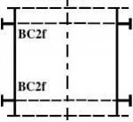
Table 5.1: Boundary conditions for shells
condition
code
BC1r term Clamped displacements displacements rotation radially restrained meridionally restrained w = 0 u = 0 βφ = 0 rotation restrained
w = 0 u = 0 BC1f meridionally restrained βφ ≠ 0 rotation free
w = 0 BC2r meridionally free u ≠ 0 βφ = 0 rotation restrained
w = 0 BC2f Pinned meridionally free u ≠ 0 βφ ≠ 0 rotation free
Free edge meridionally free BC3 w ≠ 0 u ≠ 0 βφ ≠ 0 rotation free
NOTE: The circumferential displacement v is closely linked to the displacement w normal to the surface so separate boundary conditions are not identified in paragraph (3) for these two parameters.
5.2.3 Actions and environmental influences
(1) Actions shall all be assumed to act at the shell middle surface. Eccentricities of load shall be represented by static equivalent forces and moments at the shell middle surface.
(2) Local actions and local patches of action shall not be represented by equivalent uniform loads except as detailed in section 8 (LS3 for buckling).
(3) The modelling should account for whichever of the following are relevant:
? local settlement under shell walls;
? local settlement under discrete supports;
? uniformity of support of structure;
? thermal differentials from one side of the structure to the other;
? thermal differentials from inside to outside the structure;
? wind effects on openings and penetrations;
? interaction of wind effects on groups of structures;
? connections to other structures;
? conditions during erection.
5.2.4 Stress resultants and stresses
(1) Provided that the radius to thickness ratio is greater than (r/t)min, the curvature of the shell may be ignored when calculating the stress resultants from the stresses in the shell wall.
NOTE: The National Annex may choose the value of (r/t)min. The value (r/t)min = 25 is recommended.
tiffen Eurocode3-1-6
Page 24
EN 1993-1-6: 20xx
5.3 Types of analysis
(1) The design should be based on one or more of the types of analysis given in table 5.2. Reference should be made to 2.2 for the conditions governing the use of each type of analysis.
Table 5.2: Types of shell analysis
Type of analysis
Membrane theory of shells
Linear elastic shell analysis (LA)
Linear elastic bifurcation analysis (LBA) Shell theory membrane equilibrium Material law not applicable Shell geometry perfect
Geometrically non-linear elastic analysis
(GNA)
Geometrically and materially non-linear
analysis (GMNA)
Geometrically non-linear elastic analysis
with imperfections (GNIA)
Geometrically and materially non-linear
analysis with imperfections (GMNIA)
linear bending and stretching linear bending and stretching
tiffen Eurocode3-1-6
Page 25
扩展:eurocode3 中文版 / eurocode 3 / eurocode3 中文
EN 1993-1-6: 20xx
6 Plastic limit state (LS1)
6.1 Design values of actions
(1) The design values of the actions shall be based on the most adverse relevant load combination (including the relevant γF and ψ factors).
(2) Only those actions that represent loads affecting the equilibrium of the structure need be included.
6.2 Stress design
6.2.1 Design values of stresses
(1) Although stress design is based on an elastic analysis and therefore cannot accurately predict the plastic limit state, it may be used, on the basis of the lower bound theorem, to provide a conservative assessment of the plastic collapse resistance which is used to represent the plastic limit state (see 4.1.1).
(2) The Ilyushin yield criterion may be used, as detailed in (6), that comes closer to the true plastic collapse state than a simple elastic stress evaluation.
(3) At each point in the structure the design value of the stress σeq,Ed should be taken as the highest primary stress determined in a structural analysis that considers the laws of equilibrium between imposed design load and internal forces and moments.
(4) The primary stress may be taken as the maximum value of the stresses required for equilibrium with the applied loads at a point or along a line in the shell structure.
(5) Where a membrane theory analysis is used, the resulting two dimensional field of stress resultants nx,Ed, nθ,Ed and nxθ,Ed may be represented by the equivalent design stress σeq,Ed obtained from:
1σeq,Edtnx,Ed + nθ,Ed ? nx,Ed nθ,Ed + 3nxθ,Ed. ... (6.1)
(6) Where an LA or GNA analysis is used, the resulting two dimensional field of primary stresses may be represented by the von Mises equivalent design stress: σeq,Ed =σx,Ed + σθ,Ed ? σx,Ed σθ,Ed + 3(τxθ,Ed + τxn,Ed + τθn,Ed) in which:
nmσx,Ed t(t / 4).
nmτxθ t(t / 4).
NOTE1: The above expressions give a simplified conservative equivalent stress for design purposes.
NOTE2: The values of τxn,Ed and τθn,Ed are usually very small and do not affect the plastic resistance, so they may generally be ignored.
6.2.2 Design values of resistance
(1) The von Mises design strength should be taken from:
feq,Rd = fy / γM0
(2) ... (6.5) , nmσθ,Ed t (t / 4).q, τ tq , τθt... (6.3) (6.4) ... The partial factor for resistance γM0 should be taken from the relevant application standard.
tiffen Eurocode3-1-6
Page 26
EN 1993-1-6: 20xx
(3) Where no application standard exists for the form of construction involved, or the application standard does not define the relevant values of γM0, the value of γM0 should be taken from EN 1993-1-1.
(4) The effect of fastener holes should be taken into account in accordance with 6.2.3 of EN 1993-1-1 for tension and 6.2.4 of EN 1993-1-1 for compression. For the tension check, the resistance should be based on the design value of the ultimate strength fud.
6.2.3 Stress limitation
(1) In every verification of this limit state, the design stresses should satisfy the condition:
σeq,Ed ≤ feq,Rd ... (6.6)
6.3 Design by global numerical MNA or GMNA analysis
(1) The design plastic limit resistance shall be determined as a load factor R applied to the design values of the combination of actions for the relevant load case.
(2) The design values of the actions FEd should be determined as detailed in 6.1. The relevant load cases should be formed according to the required load combinations.
(3) In an MNA or GMNA analysis based on the design yield strength fyd, the shell should be subject to the design values of the load cases detailed in (2), progressively increased by the load ratio R until the plastic limit condition is reached.
(4) Where an MNA analysis is used, the load ratio RMNA may be taken as the largest value attained in the analysis, ignoring the effect of strain hardening.
(5) Where a GMNA analysis is used, if the analysis predicts a maximum load followed by a descending path, the maximum value should be used to determine the load ratio RGMNA. Where a GMNA analysis does not predict a maximum load, but produces a progressively rising action-displacement relationship without strain hardening of the material, the load ratio RGMNA should be taken as no larger than the value at which the maximum von Mises equivalent plastic strain in the structure attains the value εmps = nmps (fyd / E).
NOTE: The National Annex may choose the value of nmps. The value nmps = 50 is recommended.
(6) The result of the analysis should produce a load ratio R greater than 1,0: that is, it should satisfy the condition:
FEd ≤ FRd
in which:
FRd = R FEd.
... (6.8) ... (6.7)
6.4 Direct design
(1) For each shell segment in the structure represented by a basic loading case as given by Annex A, the highest von Mises membrane stress σeq,Ed determined under the design values of the actions FEd should be limited to the stress resistance according to 6.2.2.
扩展:eurocode3 中文版 / eurocode 3 / eurocode3 中文
(2) For each shell or plate segment in the structure represented by a basic load case as given in Annex B, the design value of the actions FEd should not exceed the load resistance FRd based on the design yield strength fyd.
tiffen Eurocode3-1-6
Page 27
EN 1993-1-6: 20xx
(3) Where net section failure at a bolted joint is a design criterion, the design value of the actions FEd should be determined for each joint. Where the stress can be represented by a basic load case as given in Annex A, and where the resulting stress state involves only membrane stresses, FEd should not exceed the load resistance FRd based on the design ultimate strength fud (see 6.2.2(4)).
tiffen Eurocode3-1-6
Page 28
EN 1993-1-6: 20xx
7 Cyclic plasticity limit state (LS2)
7.1 Design values of actions
(1) Unless an improved definition is used, the design values of the actions for each load case should be chosen as the characteristic values of those parts of the total actions that are expected to be applied and removed more than three times in the design life of the structure.
(2) Where an elastic analysis or the expressions from Annex C are used, only the varying part of the actions between the extreme upper and lower values should be taken into account.
(3) Where a materially nonlinear computer analysis is used, the varying part of the actions between the extreme upper and lower values should be considered to act in the presence of coexistent fixed parts of the load.
7.2 Stress design
7.2.1 Design values of stress range
(1) The shell should be analysed using an LA or GNA analysis of the structure subject to the two extreme design values of the actions FEd. For each extreme load condition in the cyclic process, the stress components should be evaluated. From adjacent extremes in the cyclic process, the design values of the change in each stress component ?σx,Ed, ?σθ,Ed, ?τxθ,Ed on each shell surface and at any point in the structure should be determined. From these changes in stress, the design value of the von Mises equivalent stress change on each surface ?σeq,Ed,i should be found from:
=?σx,Ed ? ?σx,Ed ?σθ,Ed + ?σθ,Ed + 3?τxθ,Ed ?σeq,Ed,i ... (7.1)
(2) The design value of the stress range ?σeq,Ed should be taken as the largest change in the von Mises equivalent stress changes ?σeq,Ed,i, considering each shell surface in turn.
(3) At a junction between shell segments, where the analysis models the intersection of the middle surfaces and ignores the finite size of the junction, the stress range may be taken at the first physical point in the shell segment (as opposed to the value calculated at the intersection of the two middle surfaces).
NOTE: This allowance is relevant where the stress changes very rapidly close to the junction.
7.2.2 Design values of resistance
(1) The von Mises equivalent stress range resistance ?feq,Rd should be determined from:
?feq,Rd = 2 fyd
7.2.3 Stress range limitation
(1) In every verification of this limit state, the design stress range should satisfy: ... (7.2) (7.3) ?σeq,Ed ≤ ?feq,Rd ...
7.3 Design by global numerical MNA or GMNA analysis
7.3.1 Design values of total accumulated plastic strain
(1) Where a materially nonlinear global numerical analysis (MNA or GMNA) is used, the shell should be subject to the design values of the varying and fixed actions detailed in 7.1.
(2) The total accumulated von Mises equivalent plastic strain εp,eq.Ed at the end of the design life of the structure should be assessed.
tiffen Eurocode3-1-6
Page 29
EN 1993-1-6: 20xx
(3) The total accumulated von Mises equivalent plastic strain may be determined using an analysis that models all cycles of loading during the design life.
(4) Unless a more refined analysis is carried out, the total accumulated von Mises equivalent plastic strain εp,eq,Ed may be determined from:
εp,eq,Ed = n ?εp,eq,Ed
where:
n is the number of cycles of loading in the design life of the structure;
?εp,eq,Ed is the largest increment in the von Mises equivalent plastic strain during one complete
load cycle at any point in the structure, occurring after the third cycle.
(5) It may be assumed that “at any point in the structure” means at any point not closer to a notch or local discontinuity than the thickest adjacent plate thickness.
NOTE 1: It is usual to use an MNA analysis for this purpose.
NOTE 2: The National Annex may give recommendations for a more refined analysis.
7.3.2 Total accumulated plastic strain limitation
(1) Unless a more sophisticated low cycle fatigue assessment is undertaken, the design value of the total accumulated von Mises equivalent plastic strain εp,eq,Ed should satisfy the condition:
扩展:eurocode3 中文版 / eurocode 3 / eurocode3 中文
εp,eq,Ed ≤ np,eq (fyd / E)
... (7.4) ... (7.5) NOTE: The National Annex may choose the value of np,eq. The value np,eq = 5 is recommended.
7.4 Direct design
(1) For each shell segment in the structure, represented by a basic loading case as given by Annex C, the highest von Mises equivalent stress range ?σeq,Ed considering both shell surfaces under the design values of the actions FEd should be determined using the relevant expressions given in Annex C. The further assessment procedure should be as detailed in 7.2.
tiffen Eurocode3-1-6
Page 30
EN 1993-1-6: 20xx
8 Buckling limit state (LS3)
8.1 Design values of actions
(1) All relevant combinations of actions causing compressive membrane stresses or shear membrane stresses in the shell wall shall be taken into account.
8.2 Special definitions and symbols
(1) Reference should be made to the special definitions of terms concerning buckling in 1.3.5.
(2) In addition to the symbols defined in 1.4, additional symbols should be used in this section 8 as set out in (3) and (4).
(3) The stress resultant and stress quantities should be taken as follows:
nx,Ed, σx,Ed are the design values of the acting buckling-relevant meridional membrane stress
resultant and stress (positive when compression);
nθ,Ed, σθ,Ed are the design values of the acting buckling-relevant circumferential membrane (hoop) stress resultant and stress (positive when compression);
nxθ,Ed, τxθ,Ed are the design values of the acting buckling-relevant shear membrane stress resultant and stress.
(4) Buckling resistance parameters for use in stress design:
σx,Rcr is the meridional critical buckling stress;
σθ,Rcr is the circumferential critical buckling stress;
τxθ,Rcr is the shear critical buckling stress;
σx,Rk is the meridional characteristic buckling stress;
σθ,Rk is the circumferential characteristic buckling stress;
τxθ,Rk is the shear characteristic buckling stress;
σx,Rd is the meridional design buckling stress;
σθ,Rd is the circumferential design buckling stress;
τxθ,Rd is the shear design buckling stress.
that detailed in EN1993-1-1. NOTE: This is a special convention for shell design that differs from
(5) The sign convention for use with LS3 should be taken as compression positive for meridional and circumferential stresses and stress resultants.
8.3 Buckling-relevant boundary conditions
(1) For the buckling limit state, special attention should be paid to the boundary conditions which are relevant to the incremental displacements of buckling (as opposed to pre-buckling displacements). Examples of relevant boundary conditions are shown in figure 8.1, in which the codes of Table 5.1 are used.
8.4 Buckling-relevant geometrical tolerances
8.4.1 General
(1) Unless specific buckling-relevant geometrical tolerances are given in the relevant EN 1993 application parts, the following tolerance limits should be observed if LS3 is one of the ultimate limit states to be considered.
NOTE 1: The characteristic buckling stresses determined hereafter include imperfections that are based on the amplitudes and forms of geometric tolerances that are expected to be met during execution.
tiffen Eurocode3-1-6
Page 31
EN 1993-1-6: 20xx
NOTE 2: The geometric tolerances given here are those that are known to have a large impact on the safety of the structure.
(2) The fabrication tolerance quality class should be chosen as Class A, Class B or Class C according to the tolerance definitions in 8.4.2, 8.4.3, 8.4.4 and 8.4.5. The description of each class relates only to the strength evaluation.
NOTE: Until there is an execution standard that classifies geometrical tolerances according to safety considerations, these tolerances are intended to be adopted in execution.
(3) Each of the imperfection types should be classified separately: the lowest class should then govern the entire design.
(4) The different tolerance types may each be treated independently, and no interactions need normally be considered.
(5) It should be established by representative sample checks that the measurements of the geometrical imperfections stay within the geometrical tolerances stipulated in 8.4.2 to 8.4.4.
(6) Sample imperfection measurements should be undertaken on the unloaded structure (except for self weight) and, where possible, with the operational boundary conditions.
(7) If the measurements of geometrical imperfections do not satisfy the geometrical tolerances stated in 8.4.2 to 8.4.4, any correction steps, such as by straightening, should be investigated and decided individually.
NOTE: Before a decision is made in favour of straightening to reduce geometric imperfections, it should be noted that this can cause additional residual stresses. The degree to which the design buckling resistances are utilised in the design should also be considered.
扩展:eurocode3 中文版 / eurocode 3 / eurocode3 中文
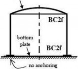
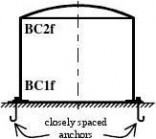
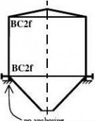
a) tank without anchors
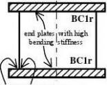
b) silo without anchors
c) tank with anchors

d) open tank with anchors e) laboratory experiment
f) section of long ring-stiffened cylinder
Figure 8.1: Schematic examples of boundary conditions for limit state LS3
tiffen Eurocode3-1-6
Page 32
EN 1993-1-6: 20xx
8.4.2 Out-of-roundness tolerance (1)
The out-of-roundness should be assessed in terms of the parameter Ur (see figure 8.2) given by:
d ? dUr =
dnom
where:
dmax dmin dnom
is the maximum measured internal diameter, is the minimum measured internal diameter, is the nominal internal diameter.
... (8.1)
(2) The measured internal diameter from a given point should be taken as the largest distance across the shell from the point to any other internal point at the same axial coordinate. An appropriate number of diameters should be measured to identify the maximum and minimum values.
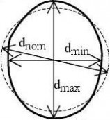
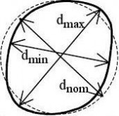
b) unsymmetrical
Figure 8.2: Measurement of diameters for assessment of out-of-roundness
(3)
The out-of-roundness parameter Ur should satisfy the condition:
Ur ≤ Ur,max
where:
Ur,max is the out-of-roundness tolerance parameter for the relevant fabrication tolerance quality
class.
NOTE: Values for the out-of-roundness tolerance parameter Ur,max may be obtained from the National Annex. The recommended values are given in Table 8.1.
... (8.2)
Table 8.1: Values for out-of-roundness tolerance parameter Ur,max
d ≤ 0,50m Fabrication Description tolerance quality class Class A Excellent 0,014
8.4.3 Accidental eccentricity tolerance
(1) At joints in shell walls perpendicular to membrane compressive forces, the accidental eccentricity should be evaluated from the measurable total eccentricity etot and the intended offset eint from:
0,50m < d < 1,25m Value of Ur,max
1,25m ≤ d
0,007 + 0,0093(1,25?d(8.3) ea = etot ? eint ...
where:
etot
eint
is the eccentricity between the middle surfaces of the joined plates (see figure 8.3c); is the intended offset between the middle surfaces of the joined plates (see figure 8.3b);
tiffen Eurocode3-1-6
Page 33
EN 1993-1-6: 20xx
ea
is the accidental eccentricity between the middle surfaces of the joined plates.
(2) The accidental eccentricity ea should satisfy the maximum permitted accidental eccentricity for the relevant fabrication tolerance quality class.
NOTE: Values for the maximum permitted accidental eccentricity may be obtained from the National Annex. The recommended values are given in Table 8.2.
Table 8.2: Values for maximum permitted accidental eccentricities
Fabrication tolerance quality class Class A Class C
accidental eccentricity
Excellent ea ≤ 2 mm ea ≤ 3 mm Normal ea ≤ 4 mm
(3) The accidental eccentricity ea should also be assessed in terms of the accidental eccentricity parameter Ue given by:
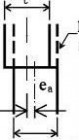
eaea
UeUe = tave
where:
tave
is the mean thickness of the thinner and thicker plates at the joint.
... (8.4)
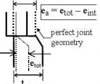
b) intended offset at a change of plate thickness without accidental eccentricity
c) total eccentricity (accidental plus intended) at change of plate thickness
a) accidental eccentricity when there is no change of plate thickness
Figure 8.3: Accidental eccentricity and intended offset at a joint
(4)
The accidental eccentricity parameter Ue should satisfy the condition:
Ue ≤ Ue,max
where:
Ue,max is the accidental eccentricity tolerance parameter for the relevant fabrication tolerance
quality class.
NOTE 1: Values for the out-of-roundness tolerance parameter Ue,max may be obtained from the National Annex. The recommended values are given in Table 8.3.
扩展:eurocode3 中文版 / eurocode 3 / eurocode3 中文
... (8.5)
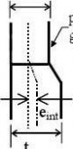
tiffen Eurocode3-1-6
Page 34
EN 1993-1-6: 20xx
Table 8.3: Values for accidental eccentricity tolerances
Fabrication tolerance quality class
Class A
NOTE 2: Intended offsets are treated within D.2.1.2 and lapped joints are treated within D.3. These two cases are not treated as imperfections within this standard.
8.4.4 Dimple tolerances
(1) A dimple measurement gauge should be used in every position (see figure 8.4) in both the meridional and circumferential directions. The meridional gauge should be straight, but the gauge for measurements in the circumferential direction should have a curvature equal to the intended radius of curvature r of the middle surface of the shell.
(2) The depth ?w0 of initial dimples in the shell wall should be measured using gauges of length lg which should be taken as follows:
a) Wherever axial compressive stresses are present, including across welds, in both the meridional and circumferential directions, measurements should be made using the gauge of length lgx given by:
lgx = 4 ... (8.6) Description Excellent Value of U0,14 b) Where circumferential compressive stresses or shear stresses occur, circumferential direction measurements should be made using the gauge of length lgθ given by:
lgθ = 2,3 (l rt)
where:
l is the axial length of the shell segment.
c) Additionally, across welds, in both the circumferential and meridional directions, the gauge length lgw should be used:
lgw = 25 t or lgw = 25 tmin , but with lgw ≤ 500mm
where:
(3)
by: tmin is the thickness of the thinnest plate at the weld. ... (8.8) 20,25, but lgθ ≤ r ... (8.7) The depth of initial dimples should be assessed in terms of the dimple parameters U0x, U0θ, U0w given
U0x = ?w0x/lgx
(4) U0θ = ?w0θ/lgθ U0w = ?w0w/lgw ... (8.9) The value of the dimple parameters U0x, U0θ, U0w should satisfy the conditions:
U0x ≤ U0,max U0θ ≤ U0,max U0w ≤ U0,max ... (8.10)
where:
U0,max is the dimple tolerance parameter for the relevant fabrication tolerance quality class.
NOTE 1: Values for the dimple tolerance parameter U0,max may be obtained from the National Annex. The recommended values are given in Table 8.4.
tiffen Eurocode3-1-6
Page 35
EN 1993-1-6: 20xx
Table 8.4: Values for dimple tolerance parameter U0,max
Fabrication tolerance quality class Class A
Description Excellent Value of U0,006
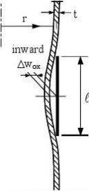
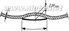
lgx
a)

b)

First measurement on a circumferential circle
gθ
c)
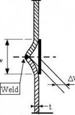
d) Second measurement on circumferential circle
low
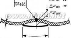
e)
gauge
lgx or lgθ or lgw
f)
Measurements on circumferential circle across
weld
Figure 8.4: Measurement of depths ?w0 of initial dimples
tiffen Eurocode3-1-6
Page 36
EN 1993-1-6: 20xx
8.4.5 Interface flatness tolerance
(1) Where another structure continuously supports a shell (such as a foundation), its deviation from flatness at the interface should not include a local slope in the circumferential direction greater than βθ.
NOTE: The National Annex may choose the value of βθ. The value βθ = 0,1% = 0,001 radians is recommended.
8.5 Stress design
8.5.1 Design values of stresses
(1) The design values of stresses σx,Ed, σθ,Ed and τxθ,Ed should be taken as the key values of compressive and shear membrane stresses obtained from linear shell analysis (LA). Under purely axisymmetric conditions of loading and support, and in other simple load cases, membrane theory may generally be used.
(2) The key values of membrane stresses should be taken as the maximum value of each stress at that axial coordinate in the structure, unless specific provisions are given in Annex D of this Standard or the relevant application part of EN 1993.
NOTE: In some cases (e.g. stepped walls under circumferential compression, see Annex D.2.3), the key values of membrane stresses are fictitious and larger than the real maximum values.
(3) For basic loading cases the membrane stresses may be taken from Annex A or Annex C.
扩展:eurocode3 中文版 / eurocode 3 / eurocode3 中文
8.5.2 Design resistance (buckling strength)
(1) The buckling resistance should be represented by the buckling stresses as defined in 1.3.5. The design buckling stresses should be obtained from:
σx,Rd = σx,Rk/γM1, σθ,Rd = σθ,Rk/γM1, τxθ,Rd = τxθ,Rk/γM1
(2)
... (8.11) The partial factor for resistance to buckling γM1 should be taken from the relevant application standard.
NOTE: The value of the partial factor γM1 may be defined in the National Annex. Where no application standard exists for the form of construction involved, or the application standard does not define the relevant values of γM1, it is recommended that the value of γM1 should not be taken as smaller than γM1 = 1,1.
(3) The characteristic buckling stresses should be obtained by multiplying the characteristic yield strength by the buckling reduction factors:
σx,Rk = χx fy,k , σθ,Rk = χθ fy,k , τxθ,Rk = χt fy,k / ... (8.12)
(4) The buckling reduction factors χx, χθ and χt should be determined as a function of the relative slenderness of the shell ?λ from:
χ = 1
ηwhen ˉ ≤ λˉ0 λ... (8.13) ˉ ? λˉλ χ = 1 ? β λ0?p ? λ?
αχˉ λ
where:
α
β
η when ˉ0 < λˉ < λˉp λˉp ≤ λˉ λ... (8.14) when ... (8.15) is the elastic imperfection reduction factor is the plastic range factor is the interaction exponent
tiffen Eurocode3-1-6
Page 37
EN 1993-1-6: 20xx
is the squash limit relative slenderness
The values of these parameters should be taken from Annex D.
NOTE: Expression (8.15) describes the elastic buckling stress, accounting for geometric imperfections. In this case, where the behaviour is entirely elastic, the characteristic buckling stresses may alternatively be determined directly from σx,Rk = αx σx,Rcr, σθ,Rk = αθ σx,Rcr, and τxθ,Rk = ατ τxθ,Rcr.
ˉp should be determined from: (5) The value of the plastic limit relative slenderness λ
ˉpλ
(6) α 1 ? β... (8.16) ?λ0 The relative shell slenderness parameters for different stress components should be determined from: ˉλ
(fy,kτxθ,Rcr ˉθfy,k / σθ,Rcr , ˉτ λλ
... (8.17) =
(7) The critical buckling stresses σx,Rcr, σθ,Rcr and τxθ,Rcr should be obtained by means of the relevant expressions in Annex D.
(8) Where no appropriate expressions are given in Annex D, the critical buckling stresses may be extracted from a numerical LBA analysis of the shell under the buckling-relevant combinations of actions defined in 8.1. For the conditions that this analysis must satisfy, see 8.6.2 (5) and (6).
8.5.3 Stress limitation (buckling strength verification)
(1) Although buckling is not a purely stress-initiated failure phenomenon, the buckling limit state, within this section, should be represented by limiting the design values of membrane stresses. The influence of bending stresses on the buckling strength may be neglected provided they arise as a result of boundary compatibility effects. In the case of bending stresses from local loads or from thermal gradients, special consideration should be given.
(2) Depending on the loading and stressing situation, one or more of the following checks for the key values of single membrane stress components should be carried out:
σx,Ed ≤ σx,Rd, σθ,Ed ≤ σθ,Rd, τxθ,Ed ≤ τxθ,Rd ... (8.18)
(3) If more than one of the three buckling-relevant membrane stress components are present under the actions under consideration, the following interaction check for the combined membrane stress state should be carried out:
σσx
?σθ
? σ????iσ?σ??σ?x,Rdx,Rdσ???θ,Rdθ,Rd?kkτ,Edτ? ? ≤ 1 τx??θ,Rd k... (8.19)
where σx,Ed, σθ,Ed and τxθ,Ed are the interaction-relevant groups of the significant values of compressive and shear membrane stresses in the shell and the values of the buckling interaction parameters kx, kθ , kτ and ki are given in Annex D.
(4) Where σx,Ed or σθ,Ed is tensile, its value should be taken as zero in expression (8.19).
NOTE: For axially compressed cylinders with internal pressure (leading to circumferential tension) special provisions are made in Annex D. The resulting value of σx,Rd accounts for both the strengthening effect of internal pressure on the elastic buckling resistance and the weakening effect of the elastic-plastic elephant’s foot phenomenon (expression D.43). If the tensile σθ,Ed is then taken as zero in expression (8.19), the buckling strength is accurately represented.
(5) The locations and values of each of the buckling-relevant membrane stresses to be used together in combination in expression (8.19) are defined in Annex D.
tiffen Eurocode3-1-6
Page 38
EN 1993-1-6: 20xx
扩展:eurocode3 中文版 / eurocode 3 / eurocode3 中文
(6) Where the shell buckling condition is not included in Annex D, the buckling interaction parameters may be conservatively estimated using:
kx = 1,0 + χx2
kθ = 1,0 + χθ2
kτ = 1,5 + 0,5 χτ2
ki = (χx χθ)2 …(8.20) …(8.21) …(8.22) …(8.23)
NOTE: These rules may sometimes be very conservative, but they include the two limiting cases which are well established as safe for a wide range of cases:
a) in very thin shells, the interaction between σx and σθ is approximately linear; and
b) in very thick shells, the interaction becomes that of von Mises.
8.6 Design by global numerical analysis using MNA and LBA analyses
8.6.1 Design value of actions
(1) The design values of actions shall be taken as in 8.1 (1).
8.6.2 Design value of resistance
(1) The design buckling resistance shall be determined as a load factor R applied to the design values of the combination of actions for the relevant load case.
(2) The design buckling resistance Rd should be obtained from the plastic reference resistance Rpl and the elastic critical buckling resistance Rcr, combining these to find the characteristic buckling resistance Rk. The partial factor γM1 should then be used to obtain the design resistance.
(3) The plastic reference resistance Rpl (see figure 8.5) should be obtained by materially non-linear analysis (MNA) as the plastic limit load under the applied combination of actions.
Rpl small displacement theory

Load factor
on design
actions
R
(4) Where it is not possible to undertake a materially non-linear analysis (MNA), the plastic reference resistance Rpl may be conservatively estimated from linear shell analysis (LA) conducted using the design values of the applied combination of actions using the following procedure. The evaluated membrane stress Figure 8.5: Definition of plastic reference resistance Rpl and critical buckling resistance Rcr derived from global MNA and LBA analyses
tiffen Eurocode3-1-6
Page 39
EN 1993-1-6: 20xx
resultants nx,Ed, nθ,Ed and nxθ,Ed at any point in the shell should be used to find the plastic reference resistance from: t f ... (8.24) nx,Ed ? nx,Ednθ,Ed + nθ,Ed + 3nxθ,Ed
The lowest value of plastic resistance so calculated should be taken as the estimate of the plastic reference resistance Rpl.
NOTE: A safe estimate of Rpl can usually be obtained by applying expression (8.24) in turn at the three points in the shell where each of the three buckling-relevant membrane stress resultants attains its highest value, and using the lowest of these three estimates as the relevant value of Rpl.
(5) The critical buckling resistance Rcr should be determined from an eigenvalue analysis (LBA) applied to the linear elastic calculated stress state in the geometrically perfect shell (LA) under the design values of the load combination. The lowest eigenvalue (bifurcation load factor) should be taken as the critical buckling resistance Rcr, see figure 8.5.
(6) It should be verified that the eigenvalue algorithm that is used is reliable at finding the eigenmode that leads to the lowest eigenvalue. In cases of doubt, neighbouring eigenvalues and their eigenmodes should be calculated to obtain a fuller insight into the bifurcation behaviour of the shell. The analysis should be carried out using software that has been authenticated against benchmark cases with physically similar buckling characteristics.
ˉov for the complete shell should be determined from: (7) The overall relative slenderness λ
ˉov = Rpl / Rcr λ... (8.25)
ˉov, λˉov,0, αov, βov, ηov) (8) The overall buckling reduction factor χov should be determined as χov = f(λ
using 8.5.2 (4), in which αov is the overall elastic imperfection factor, βov is the plastic range factor, ηov is the
ˉov,0 is the squash limit relative slenderness. interaction exponent and λ
ˉov,0, αov, βov and ηov should take account of the imperfection sensitivity, (9) The evaluation of the factors λ
geometric nonlinearity and other aspects of the particular shell buckling case. Conservative values for these parameters should be determined by comparison with known shell buckling cases (see Annex D) that have similar buckling modes, similar imperfection sensitivity, similar geometric nonlinearity, similar yielding sensitivity and similar postbuckling behaviour. The value of αov should also take account of the appropriate fabrication tolerance quality class.
NOTE: Care should be taken in choosing an appropriate value of αov when this approach is used on shell geometries and loading cases where snap-through buckling may occur. Such cases include shallow conical and spherical caps and domes under external pressure or on supports that can displace radially, and assemblies of cylindrical and conical shell segments without ring stiffeners at the meridional junctions and which are loaded meridionally.
扩展:eurocode3 中文版 / eurocode 3 / eurocode3 中文
The commonly reported elastic shell buckling loads for these special cases are normally based on geometrically nonlinear analysis applied to a perfect or imperfect geometry. By contrast, the methodology used here adopts the linear bifurcation load as the reference critical buckling resistance, and this is often much higher than the snap-through load. The design calculation must account for these two sources of reduced resistance by an appropriate choice of the overall imperfection reduction factor αov. This choice must include the effect of both the geometric nonlinearity that leads to snap-through and the additional strength reduction caused by geometric imperfections.
(10) If the provisions of (9) cannot be achieved beyond reasonable doubt, appropriate tests should be carried out (see EN 1990, Annex D).
ˉov,0 are not available according to (9) or (10), the values for an (11) If specific values of αov, βov, ηov and λ
axially compressed unstiffened cylinder may be adopted (see D.1.2.2).
tiffen Eurocode3-1-6
Page 40
EN 1993-1-6: 20xx
(12) The characteristic buckling resistance should be obtained from:
Rk = χov Rpl ... (8.26)
where:
(13) The design buckling resistance Rd should be obtained from: Rpl is the plastic reference resistance.
(8.27) Rd = Rk/γM1 ...
where:
8.6.3 Buckling strength verification
(1) It should be verified that:
Fd ≤ Rd Fd or Rd ≥ 1
... (8.28) γM1 is the partial factor for resistance to buckling according to 8.5.2 (2).
8.7 Design by global numerical GMNIA analysis
8.7.1 Design values of actions
(1) The design values of actions shall be taken as in 8.1 (1).
8.7.2 Design value of resistance
(1) The design buckling resistance shall be determined as a load factor R applied to the design values Fd of the combination of actions for the relevant load case.
(2) The characteristic buckling resistance Rk should be found from the imperfect elastic-plastic critical buckling resistance RGMNIA, adjusted by the calibration factor kGMNIA. The design buckling resistance Rd should then be found using the partial factor γM1.
(3) To determine the imperfect elastic-plastic critical buckling resistance RGMNIA, a GMNIA analysis of the geometrically imperfect shell under the applied combination of actions should be carried out, accompanied by an eigenvalue analysis to detect possible bifurcations in the load path.
NOTE: If possible, the eigenvalue analysis should use the deformation theory of plasticity, since the flow theory of plasticity can give a considerable overestimate of the elastic-plastic buckling resistance for certain problems.
(4) An LBA analysis should first be performed on the perfect structure to determine the perfect elastic critical buckling resistance RLBA. An MNA should next be performed on the perfect structure to determine the perfect plastic collapse resistance RMNA. These two resistances should then be used to establish the overall relative
ˉov for the complete shell according to expression 8.25. slenderness λ
(5) A GMNA analysis should then be performed on the perfect structure to determine the perfect elastic-plastic critical buckling resistance RGMNA. This resistance should be used later to verify that the effect of the chosen geometric imperfections has a sufficiently deleterious effect to give confidence that the lowest resistance has been obtained. The GMNA analysis should be carried out under the applied combination of actions, accompanied by an eigenvalue analysis to detect possible bifurcations in the load path.
(6) The imperfect elastic-plastic critical buckling resistance RGMNIA should be found as the lowest load factor R obtained from the three following criteria C1, C2 and C3, see figure 8.6:
tiffen Eurocode3-1-6
Page 41
EN 1993-1-6: 20xx
? Criterion C1: The maximum load factor on the load-deformation-curve (limit load);
? Criterion C2: The bifurcation load factor, where this occurs during the loading path before reaching the limit point of the load-deformation-curve;
? Criterion C3: The largest tolerable deformation, where this occurs during the loading path before reaching the bifurcation load or the limit load.
(7) The largest tolerable deformation should be assessed relative to the conditions of the individual structure. If no other value is available, the largest tolerable deformation may be deemed to have been reached when the greatest local rotation of the shell (slope of the surface relative to its original geometry) attains the value β.
NOTE: The National Annex may choose the value of β. The value β = 0,1 radians is recommended.
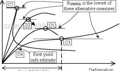
扩展:eurocode3 中文版 / eurocode 3 / eurocode3 中文
Load factor
on design
actions
Rdeformation Figure 8.6: Definition of buckling resistance from global GMNIA analysis
(8) A conservative assessment of the resistance RGMNIA may be obtained using a GNIA analysis of the geometrically imperfect shell under the applied combination of actions. In this case, the following criterion should be used to determine the lowest load factor R:
? Criterion C4: The load factor at which the equivalent stress at the most highly stressed point on the shell surface reaches the design value of the yield stress fy/γM0 (figure 8.6).
NOTE: It should be noted that GMNA, GMNIA and GNIA analyses must always be undertaken with regular eigenvalue checks to ensure that any possible bifurcation on the load path is detected.
(9) In formulating the GMNIA (or GNIA) analysis, appropriate allowances should be incorporated to cover the effects of imperfections that cannot be avoided in practice, including:
a) geometric imperfections, such as:
? deviations from the nominal geometric shape of the middle surface (pre-deformations, out-of-roundness); ? irregularities at and near welds (minor eccentricities, shrinkage depressions, rolling curvature errors); ? deviations from nominal thickness;
? lack of evenness of supports.
b) material imperfections, such as:
? residual stresses caused by rolling, pressing, welding, straightening etc.;
? inhomogeneities and anisotropies.
tiffen Eurocode3-1-6
Page 42
EN 1993-1-6: 20xx
NOTE: Further possible negative influences on the critical buckling resistance RGMNIA, such as ground settlements or flexibilities of connections or supports, are not classed as imperfections in the sense of these provisions.
(10) Imperfections should be allowed for in the GMNIA analysis by including appropriate additional quantities in the analytical model for the numerical computation.
(11) The imperfections should generally be introduced by means of equivalent geometric imperfections in the form of initial shape deviations perpendicular to the middle surface of the perfect shell, unless a better technique is used. The middle surface of the geometrically imperfect shell should be obtained by superposition of the equivalent geometric imperfections on the perfect shell geometry.
(12) The pattern of the equivalent geometric imperfections should be chosen in such a form that it has the most unfavourable effect on the buckling resistance RGMNIA of the shell. If the most unfavourable pattern cannot be readily identified beyond reasonable doubt, the analysis should be carried out for a sufficient number of different imperfection patterns, and the worst case (lowest value of RGMNIA) should be identified.
(13) The eigenmode-affine pattern should be used unless a different unfavourable pattern can be justified.
NOTE: The eigenmode affine pattern is the critical buckling mode associated with the elastic critical buckling resistance Rcr based on an LBA analysis of the perfect shell.
(14) The pattern of the equivalent geometric imperfections should, if practicable, reflect the constructional detailing and the boundary conditions in an unfavourable manner.
(15) Notwithstanding (13) and (14), patterns may be excluded from the investigation if they can be eliminated as unrealistic because of the method of fabrication, manufacture or erection.
(16) Modification of the adopted mode of geometric imperfections to include realistic structural details (such as axisymmetric weld depressions) should be explored.
NOTE: The National Annex may define additional requirements for the assessment of appropriate patterns of imperfections.
(17) The sign of the equivalent geometric imperfections should be chosen in such a manner that the maximum initial shape deviations are unfavourably oriented towards the centre of the shell curvature.
(18) The amplitude of the adopted equivalent geometric imperfection form should be taken as dependent on the fabrication tolerance quality class. The maximum deviation of the geometry of the equivalent imperfection from the perfect shape ?w0,eff should be the larger of ?w0,eff,1 and ?w0,eff,2, where:
?w0,eff,1 = lg Un1 ... (8.29)
(8.30) ?w0,eff,2 = ni t Un2 ...
where:
lg is all relevant gauge lengths according to 8.4.4 (2);
t is the local shell wall thickness;
is a multiplier to achieve an appropriate tolerance level; ni
Un1 and Un2 are the dimple imperfection amplitudes for the relevant fabrication tolerance quality
class.
value ni = 25 is recommended. NOTE 1: The National Annex may choose the value of ni. The NOTE 2: Values for the dimple tolerance parameter Un1 and Un2 may be obtained from the National Annex. The recommended values are given in Table 8.5.
tiffen Eurocode3-1-6
扩展:eurocode3 中文版 / eurocode 3 / eurocode3 中文
Page 43
EN 1993-1-6: 20xx
Table 8.5: Values for initial dimple imperfection amplitudes Un1 and Un2
Fabrication tolerance quality class
Class A
Description Excellent Value of U0,010 Value of U0,010
(19) The amplitude of the geometric imperfection in the adopted pattern of the equivalent geometric imperfection should be interpreted in a manner which is consistent with the gauge length method, set out in
8.4.4 (2), by which it is defined.
(20) Additionally, it should be verified that an analysis that adopts an imperfection whose amplitude is 10% smaller than the value ?w0,eff found in (18) does not yield a lower value for RGMNIA. If a lower value is obtained, the procedure should be iterated to find the lowest value of RGMNIA as the amplitude is varied.
(21) If follower load effects are possible, either they should be incorporated in the analysis, or it should be verified that their influence is negligible.
(22) For each calculated value of the buckling resistance RGMNIA, the ratio of the imperfect to perfect resistance (RGMNIA/RGMNA) should be determined and compared with values of α found using the procedures of 8.5 and Annex D, to verify that the chosen geometric imperfection has a deleterious effect that is comparable with that obtained from a lower bound to test results.
NOTE: Where the resistance is dominated by plasticity effects, the ratio (RGMNIA/RGMNA) will be much larger than α, and no close comparison can be expected. However, where the resistance is controlled by buckling phenomena that are substantially elastic, the ratio (RGMNIA/RGMNA) should be only a little higher than the value determined by hand calculation, and the factors leading to the higher value should be considered.
(23) The reliability of the numerically determined critical buckling resistance RGMNIA should be checked by one of the following alternative methods:
a) by using the same program to calculate values RGMNIA,check for other shell buckling cases for which characteristic buckling resistance values Rk,known,check are known. The check cases should use basically similar imperfection assumptions and be similar in their buckling controlling parameters (such as relative shell slenderness, postbuckling behaviour, imperfection-sensitivity, geometric nonlinearity and material behaviour);
b) by comparison of calculated values (RGMNIA,check) against test results (Rtest,known,check). The check cases should satisfy the same similarity conditions given in (a).
NOTE: Other shell buckling cases for which the characteristic buckling resistance values Rk,known,check are known may be found from the scientific literature on shell buckling. It should be noted that the hand calculations of 8.5 and Annex D are derived as general lower bounds on test results, and these sometimes lead to such low assessed values for the characteristic buckling resistance that they cannot be easily obtained numerically.
(24) Depending on the results of the reliability checks, the calibration factor kGMNIA should be evaluated, as appropriate, from:
RRRGMNIA,checkRGMNIA,check ... (8.31)
where:
Rk,known,check is
Rtest,known,check is
RGMNIA,check is the known characteristic value; the known test result; the calculation outcome for the check buckling case or the test buckling case,
as appropriate.
(25) Where test results are used to determine kGMNIA, and the calculated value of kGMNIA exceeds 1,0, the adopted value should be kGMNIA = 1,0.
tiffen Eurocode3-1-6
Page 44
EN 1993-1-6: 20xx
(26) Where a known characteristic value based on existing established theory is used to determine kGMNIA, and the calculated value of kGMNIA lies outside the range 0,8 < kGMNIA 1,2, this procedure should not be used. The GMNIA result should be deemed invalid, and further calculations undertaken to establish the causes of the discrepancy.
(27) The characteristic buckling resistance should be obtained from:
Rk = kGMNIA RGMNIA ... (8.32)
where:
RGMNIA is the calculated imperfect elastic-plastic critical buckling resistance;
kGMNIA is the calibration factor.
8.7.3 Buckling strength verification
(1) The design buckling resistance Rd should be obtained from:
Rd = Rk/γM1 ...
where:
γ
M1 is the partial factor for resistance to buckling according to 8.5.2 (2).
(2) It should be verified that:
Fd ≤ Rd Fd or Rd ≥ 1
(8.33) ... (8.34)
tiffen Eurocode3-1-6
Page 45
EN 1993-1-6: 20xx
9 Fatigue limit state (LS4)
9.1 Design values of actions
(1) The design values of the actions for each load case shall be taken as the varying parts of the total action representing the anticipated action spectrum throughout the design life of the structure.
扩展:eurocode3 中文版 / eurocode 3 / eurocode3 中文
(2) The relevant action spectra should be obtained from EN 1991 in accordance with the definitions given in the appropriate application parts of EN 1993.
9.2 Stress design
9.2.1 General
(1)
(2)
The fatigue assessment presented in EN 1993-1-9 should be used, except as provided here. The partial factor for resistance to fatigue γMf should be taken from the relevant application standard.
NOTE: The value of the partial factor γMf may be defined in the National Annex. Where no application standard exists for the form of construction involved, or the application standard does not define the relevant values of γMf, the value of γMf should be taken from EN 1993-1-9. It is recommended that the value of γMf should not be taken as smaller than γMf = 1,1.
9.2.2 Design values of stress range
(1) Stresses shall be determined by a linear elastic analysis of the structure subject to the design values of the fatigue actions.
(2) In each verification of the limit state, the design value of the fatigue stress should be taken as the larger stress range ?σ of the values on the two surfaces of the shell, and based on the sum of the primary and the secondary stresses.
(3) Depending upon the fatigue assessment carried out according to EN 1993-1-9, either nominal stress ranges or geometric stress ranges should be evaluated.
(4) Nominal stress ranges may be used if 9.2.3 (2) is adopted.
(5) Geometric stress ranges should be used for construction details that differ from those of 9.2.3 (2).
(6) The geometric stress range takes into account only the overall geometry of the joint, excluding local stresses due to the weld geometry and internal weld effects. It may be determined by use of geometrical stress concentration factors given by expressions.
(7) Stresses used for the fatigue design of construction details with linear geometric orientation should be resolved into components transverse to and parallel to the axis of the detail.
9.2.3 Design values of resistance (fatigue strength)
(1) The design values of resistance obtained from the following may be applied to structural steels in the temperature range up to 150° C.
(2) The fatigue resistance of construction details commonly found in shell structures shall be obtained from EN 1993-3-2 in classes in terms of the stress range ?σR, in which the values are additionally classified according to the quality of the welds.
(3) The fatigue resistance of the detail classes should be obtained from EN 1993-1-9.
tiffen Eurocode3-1-6
Page 46
EN 1993-1-6: 20xx
9.2.4 Stress range limitation
(1) In every verification of this limit state, the design stress range should satisfy the condition:
γFf ?σE ≤ ?σR / γMf ... (9.1)
where:
γFf
γMf
?σE
?σR
(2) is is is is the partial factor for the fatigue loading the partial factor for the fatigue resistance the equivalent constant amplitude stress range of the design stress spectrum the fatigue strength stress range for the relevant detail category and the number of cycles of the stress spectrum As an alternative to (1), a cumulative damage assessment may be made using the Palmgren-Miner rule:
Dd ≤ 1 ... (9.2)
in which:
Dd = Σ ni / Ni ... (9.3)
where:
ni
Ni is is the number of cycles of the stress range ?σi
the number of cycles of the stress range γFf γMf ?σi to cause failure for the relevant
detail category
(3) In the case of combination of normal and shear stress ranges the combined effects should be considered in accordance with EN 1993-1-9.
9.3 Design by global numerical LA or GNA analysis
(1) The fatigue design on the basis of an elastic analysis (LA or GNA analysis) should follow the provisions given in 9.2 for stress design. However, the stress ranges due to the fatigue loading should be determined by means of a shell bending analysis, including the geometric discontinuities of joints in constructional details.
(2) If a three dimensional finite element analysis is used, the notch effects due to the local weld geometry should be eliminated.
tiffen Eurocode3-1-6
Page 47
EN 1993-1-6: 20xx
ANNEX A (normative)
Membrane theory stresses in shells
A.1 General
A.1.1 Action effects and resistances
The action effects or resistances calculated using the expressions in this annex may be assumed to provide characteristic values of the action effect or resistance when characteristic values of the actions, geometric parameters and material properties are adopted.
A.1.2 Notation
The notation used in this annex for the geometrical dimensions, stresses and loads follows 1.4, and in addition, the following notation is used.
Roman upper case letters
Fx axial load applied to the cylinder
扩展:eurocode3 中文版 / eurocode 3 / eurocode3 中文
M global bending moment applied to the complete cylinder (not to be confused with the
moment per unit width in the shell wall m)
global torque applied to the complete cylinder Mt
V global transverse shear applied to the complete cylinder
Roman lower case letters
g unit weight of the material of the shell
distributed normal pressure pn
distributed axial traction on cylinder wall px
Greek lower case letters
φ meridional slope angle
axial or meridional membrane stress (= nx/t) σx
circumferential membrane stress (= nθ/t) σθ
τ membrane shear stress (= nxθ/t)
A.1.3 Boundary conditions
(1) The boundary condition notations should be taken as detailed in 2.3.
(2) For these expressions to be strictly valid, the boundary conditions for cylinders should be taken as radially free at both ends, axially supported at one end, and rotationally restrained at both ends.
(3) For truncated cones, the boundary conditions should be understood to include components of loading transverse to the shell wall, so that the combined stress resultant introduced into the shell is solely in the direction of the shell meridian.
(4) The boundary conditions for these expressions to be strictly valid for cones should be taken as radially free at both ends, meridionally supported at one end, and rotationally restrained at both ends.
A.1.4 Sign convention
(1) The sign convention for stresses σ should be taken everywhere as tension positive, though some of the figures illustrate cases in which the external load is applied in the opposite sense.
tiffen Eurocode3-1-6
Page 48
EN 1993-1-6: 20xx
A.2 Unstiffened Cylindrical Shells A.2.1 Uniform axial load
A.2.2 Axial load A.2.3 Friction load


from bending

πr Px
Px,max
πr2 Px,max
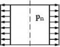
Px,max
M = πr2 Px,max
Fx = 2πr Px
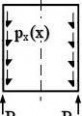
F
σx = ? 2πrt
M
σx = ± πrt
l1
σx = ?
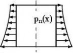
??px dx
A.2.4 Uniform internal pressure
A.2.5 Variable internal pressure
r
σθ = pn
σθ(x) = pn
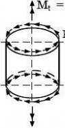
(x)A.2.6 Uniform shear from torsion
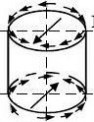
A.2.7 Sinusoidal shear
from transverse force
2
πr Pθ
θ
V = πr Pθ,max
θ(θ)
M
τ = 2πrt
τmax = ±
Vπrt
tiffen Eurocode3-1-6
Page 49
EN 1993-1-6: 20xx
A.3 Unstiffened Conical Shells
A.3.1 Uniform axial load
A.3.2 Axial load A.3.3 Friction load
from bending
πr2 Pz,2


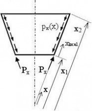
M = πr2 Pz,2,max
Pz,2,max
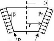
2
z,2z,1
πr1 Pz,1
P2
M = πr1 Pz,1,max
x1 F
σx = ?2π
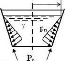
r t cosβ σθ = 0
M
σx,max = ± πr t cosβ σθ = 0
sinβ
x2 =
sinβ
x21 p xdx σx1 = ? xt?
1?x
x1 σθ = 0
A.3.4 Uniform internal pressure
A.3.5 Linearly varying
internal pressure
r??r2
σx = ? pn ? 1?? 2tcosβ??r
σθ = pn
t cosβ
r2S is the radius at the fluid surface
r?γ rr??r2
σx = ? ? 3? + ?
?t sinβ????
γ r
? r) σθ = +
t sinβ2S
tiffen Eurocode3-1-6
Page 50
EN 1993-1-6: 20xx
A.3.6 Uniform shear from torsion
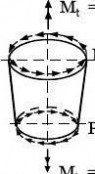
πr2
2 Pθ,2
θ,2
θ,1
πr12
Pθ,1
τ =
扩展:eurocode3 中文版 / eurocode 3 / eurocode3 中文
M2πrt
A.4 Unstiffened Spherical Shells
A.4.1 Uniform internal pressure A.4.2
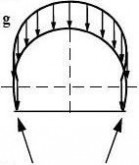
σx = pr
σθ = pr
A.3.7 Sinusoidal shear
from transverse force
V = πr2 Pθ,2,max
Pθ,2(θ)
θ,1(θ)
V = πr1 Pθ,1,max

τmax = ± V
πrt
Uniform self-weight load
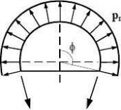
σx = ? gr
1?1 + cosφ ?
σθ = ? gr?1t?cosφ ?1 + cosφ ?
tiffen Eurocode3-1-6
Page 51
EN 1993-1-6: 20xx
ANNEX B (normative)
Additional expressions for plastic collapse resistances
B.1 General
B.1.1 Resistances
The resistances calculated using the expressions in this annex may be assumed to provide characteristic values of the resistance when characteristic values of the geometric parameters and material properties are adopted.
B.1.2 Notation
The notation used in this annex for the geometrical dimensions, stresses and loads follows 1.4, and in addition, the following notation is used.
Roman upper case letters
Ar cross-sectional area of a ring
characteristic value of small deflection theory plastic mechanism resistance PR
Roman lower case letters
b thickness of a ring
l effective length of shell which acts with a ring r radius of the cylinder
se dimensionless von Mises equivalent stress parameter
dimensionless combined stress parameter sm
dimensionless axial stress parameter sx
dimensionless circumferential stress parameter sθ
Subscripts
r relating to a ring
R resistance
B.1.3 Boundary conditions
(1)
(2)
The boundary condition notations should be taken as detailed in 5.2.2. The term “clamped” should be taken to refer to BC1r and the term “pinned” to refer to BC2f.
tiffen Eurocode3-1-6
Page 52
EN 1993-1-6: 20xx
B.2 Unstiffened cylindrical shells
B.2.1 Cylinder: Radial line load
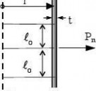
Reference quantities:
lo
The plastic resistance PnR (force per unit circumference) is given by:
Ptf yor B.2.2
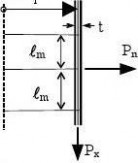

x
Reference quantities:
Psx = fyRange of applicability:
?1 ≤ sx ≤ +1
Dependent parameters:
If Pn > 0 (outward)
If Pn < 0 (inward)
sm = AA + 4(1 ? sx) lo then: A = + sx ? 1,50 then: A = ? sx ? 1,50
If sx ≠ 0
tPf yr2lmthen: lm = sm lo The plastic resistance PnR (force per unit circumference) is given by:
tiffen Eurocode3-1-6
Page 53
EN 1993-1-6: 20xx
B.2.3 Cylinder: Radial line load, constant internal pressure and axial load
x

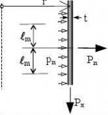
Reference quantities:
Psx = y
prsθ = y
lo Range of applicability:
?1 ≤ sx ≤ +1
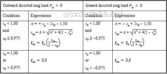
se = sθ + s x ? sxsθ ?1 ≤ sθ ≤ +1
The plastic resistance is given by (Pn and pn always positive outwards):
tPp = fnyrm
tiffen Eurocode3-1-6
Page 54
EN 1993-1-6: 20xx
B.3 Ring stiffened cylindrical shells
B.3.1 Ring stiffened Cylinder: Radial line load
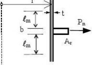
The plastic resistance PnRA + (b + 2l)t PnR = fy r
l

m = lo = 0,975
B.3.2 Ring stiffened Cylinder: Radial line load and axial load
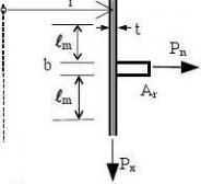
x
Reference quantities:
Psx = f yt
Range of applicability:
?1 ≤ sx ≤ +1
Dependent parameters:
If Pn > 0
If Pn < 0
) sm = AA + 4(1 ? sxlo then: A = + sx ? 1,50 then: A = ? sx ? 1,50
If sx ≠ 0
A + (b + 2l)t PnR = fy rthen: lm = sm lo The plastic resistance PnR (force per unit circumference) is given by:
tiffen Eurocode3-1-6
[www.61k.com]扩展:eurocode3 中文版 / eurocode 3 / eurocode3 中文
扩展:eurocode3 中文版 / eurocode 3 / eurocode3 中文
四 : 顿渐论(1-6)
1.
人与人之间,最低温度
是爱的透明与不爱的
英明,而暧昧使战争
的不确定宛如裹尸布。
那些内裤绣十字架的,( 文章阅读网:www.61k.com )
包藏什么爱的纯洁性呢。
2017年3月15日于茶窖
2.
啊人性磨损之处
不屈的,原来是气
诗闷了,周期不长了
气在叹息,词何以算计
2017年3月15日于茶窖
3.
即使作一个国王,他的
财富,只是一组数字。
所有权力,与欲望,
抵不住信仰之跃。
没有信仰这一跃,
缺席的,可能酿成
心灵的停电;阻碍的,
可能不止是思维,和成长。
2017年3月15日于茶窖
4.
或许,寂寞是纯棉的。
或许,寂寞是泡沫的。
或许,寂寞是猪皮的。
谁知道呢?假想而已。
2017年3月15日于茶窖
5.
人诗不是合一,而是
反水,至于谁反谁的水,
只有天知道,因为当事人
可能也不清楚,唯唯,否否。
2017年3月16日于茶窖
6.
进入城市,或是被进入,
你只能选择一个骨灰盒。
这个盒子仿佛密码的组合,
麻痹天空,把密码麻醉了吗。
2017年3月16日于茶窖
本文标题:1-6-NeotecWELLFLOV8.1.661阅读| 精彩专题| 最新文章| 热门文章| 苏ICP备13036349号-1